
February, 2002.
Comets are pyrotechnic devices consisting of powder pressed under extreme pressure in a hydraulic press into a single grain in the shape of a solid cylinder. This project will create a 5-piece tool set for pressing comets, consisting of a base, cylinder, sleeve, piston, and insert, all machined from aluminum.
The inside diameter of the cylinder will be 1.625 inches, which creates comets suitable for the 1.75 inch HDPE mortars sold with Class C shell kits. The base will provide a flat surface to mate to the bottom of the cylinder. Below, we start with 1/4-inch thick aluminum plate. The piece has been cut and milled to a clean 2.7 inch square using the edge-milling mode of the mill-drill. To mount this piece on the minilathe for facing, I drilled and tapped two 6-1.0 mm holes on the diagonal, with 66 mm spacing, which fits the headstock spindle mounting holes on the minilathe. To locate these holes on the stock with a centerpunch, I first scored the diagonals with a straightedge and scribe, and then from the center crossing scored a 33 mm radius with scribe points on a compass.
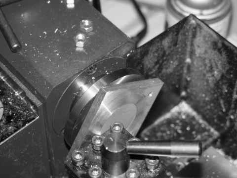
Below is the square plate mounted directly onto the spindle as if it were a faceplate, with no intervening chuck or faceplate. The attachment uses the same 6-1.0 x 25 mm socket setscrews and nuts used to mount a faceplace. This avoids any clamps projecting over the work, and permits facing the entire surface of the piece. The setscrews mate into the threaded holes on the plate, and are inserted with their heads below the plate surface, sufficient to clear the material which is about to be faced off. I cleaned the mating faces of the work and spindle, to get a good friction clamp from the screws.
I found two screws alone were enough to hold the stock firmly enough for the operations that followed. The lathe spindle provides 4 holes at 90-degree positions and 3 holes at 120-degree positions, one hole being shared, for a total of 6 holes. The faceplates and 3-jaw chucks available for this lathe use the 120-degree holes, and the 4-jaw chuck uses the 90-degree holes. The holes themselves are about 6.9 mm dia, which leaves a full 1 mm of play for the 5.9 mm actual dia of the 6-1.0 metric screws. Perhaps the lathe designers intended the spindle to permit the use of 0.25 in mounting screws.
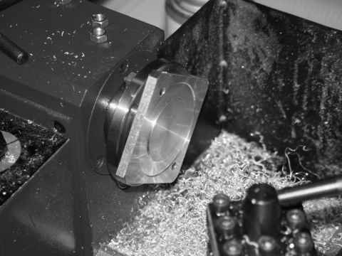
The machining of the base starts with the minimal cut to face the entire plate. A 3/8 in depression ring is then cut about 0.040 in deep, which will receive the mating cylinder. The ID of the depressed ring cut is 1.610 in, slightly under the planned 1.625 in ID of the cylinder which will mate to this surface. Using a 60-degree carbide bit leaves beveled edges on the steps of the depression. I also turned off the sharp corners of the square.
Below, machining of the base is finished. After removing the piece from the lathe, the edges are dressed by hand with a steel tool bit to remove the burrs.
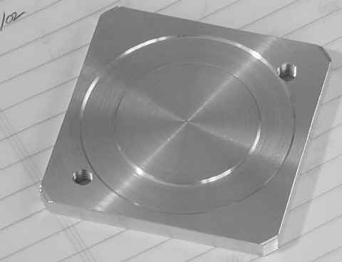
Below is the finished base. The rounded corners show some waves; this is due to the bit not running true as I ran out the cross-slide leadscrew. The appearance is almost as if the outside of the corners had been threaded. I had not adjusted the cross-slide to remove this wave, but the effect is almost aesthetically decorative and does not degrade the function.
Note also that the ring cut is not exactly centered between the mounting holes. This is due to the play from the setscrews in the slightly larger spindle holes. While this does not affect function, before cutting, I should have centered the rough piece on the spindle using the point of the bit as a reference. This would have centered the ring better, for aesthetics.
The die is a simple solid cylinder which mates to the inside diameter of the cylinder halves. Rather than use stock aluminum, I melted and cast the cylinder from scrap aluminum.
The first step in casting is to create the green sand mold. I am in the early stages of learning that craft, and have not yet made any of the tooling. But casting this simple cylinder will not require anything but the simplest sand-casting components.
I mix my own green sand, starting with blasting sand from Home Depot, which is a silica sand of an appropriate grain shape and size. To this I add finely ground bentonite clay, which is nothing more than kitty litter (cat litter) processed in a Sponenberg-style ball mill. These are blended in a plastic mixing bowl, with a few shpritzes of water from a spray bottle, just enough to get it clumping. I use a recipe of 8 parts sand, 1 part clay, and about 1/2 part water, by weight. It works great. Some recipes call for increasing the proportion of clay to 2 parts; I suppose this may depend on the character of the clay used.
Not all cat litter is bentonite clay; it took me a few tries to find that the cheap Publix (Florida) grocery store brand was ideal. The best test for a suitable clay (short of processing it all the way to green sand) is to grind a small amount to a very fine powder, and compress it with about 5000 psi of force, such as with a small cylinder and piston in an arbor press or even hammered with a mallet. Bentonite clay will consolidate into a very hard pellet that can't be broken with your fingers, and is hard to pick apart with the point of an awl.
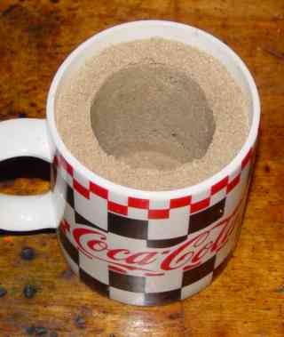
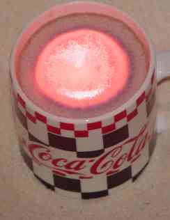
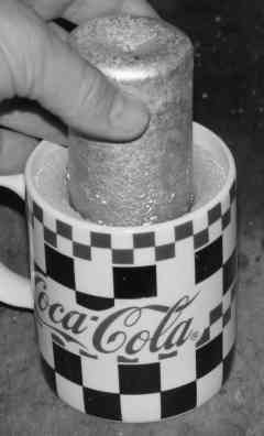
Below is the container I used for casting, a coffee mug. I formed the mold by using a piece of 1.5 inch PVC pipe for the "model". The OD of pipe is about 1.9 inches, which should leave plenty of extra material to machine the casting down to the finished size of 1.625 inches.
Below is my coffee can foundry getting fired up for the melt. I improvised it from a homemade recipe for castable refractory. I made the refractory lining by first casting a mix of sodium silicate furnace cement (from Grainger) and perlite aggregate (from Home Depot), in a proportion of about 1:4 v/v, using an empty 2-liter soda bottle for the core of the casting mold. Then for strength I plastered on a lining of the cement thinned with about 10 percent by volume of water. The lid may be cast in a plastic lid from a storage tub or other suitable shape. You can see the lid has broken during this session, exposing the perlite beads that had been covered with a layer of furnace cement. This was not so much of a problem, because I could put the pieces in place, and leave a crack in the center through which I could feed the scrap into the melt. The propane burner is an improvised design after Ron Reil's technique.
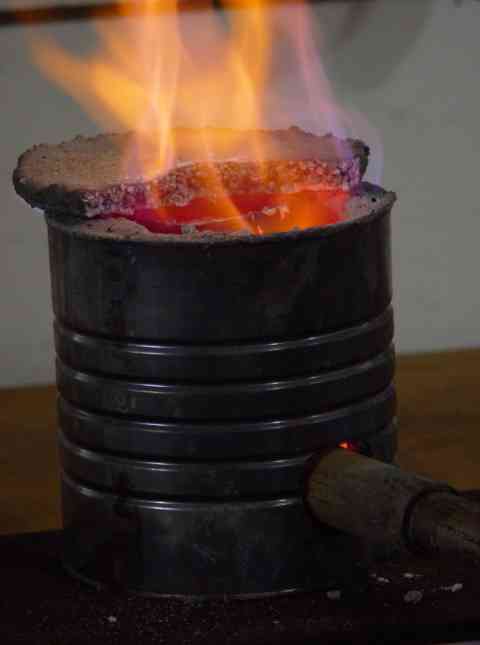
A steel soup can serves as a one-time-use crucible. Below you can see the crucible is at red heat, with some aluminum ingots left over from a previous melt starting to thaw.
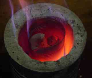
Once the ingots melted and formed a puddle in the bottom of the crucible, I started adding lengths of scrap aluminum electric cable scrounged from a trash pile. After some minutes more for heating, I had about 3 pounds of molten aluminum in the crucible. Since the cylinder only needed about 0.8 pounds, computed from its volume of about 8 cubic inches and my 10 cu in/lb rule-of-thumb for aluminum, the can was mostly still full after the pour.
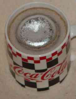
Below is the freshly-poured, and still molten, aluminum in the mold (left), and after cooling (right). The metal shrinks as it cools, creating a dimple in the center of the casting, but this will eventually be machined off. I've placed the mold in a bucket of sand during the pour; if the cup were to break, the sand will safely contain the spilled metal.
Returning to the foundry, to pour the remaining 2 pounds of melt, I discovered that my soup-can crucible had sprung a small leak on the bottom. Apparently one cannot keep a steel can at that temperature for as long as I did without it starting to shed scale and eventually perforating. About 1 pound of molten aluminum had exited the crucible and puddled on the lining in the bottom of the foundry. This interfered with the circulation of hot propane, causing the remaining aluminum to cool and freeze in the crucible. I had to remove the crucible without pouring ingots. After the puddle froze I was able to remove it from the foundry lining. These big pieces will have to be broken up to be used in a future melt.
Foundry work is hazardous, even on this small scale. The metal is so hot that a spill is nearly uncontrollable. The heat of the metal is such that it can cause molds or other containers to crack and initiate a spill. Introducing moisture into the melt (such as from feeding wet scrap) can cause a steam burst to throw metal into the area. Every step of the handling must be done via tools and gloves. This is not a hobby for the timid.
Considering the time involved, casting from scrap is not even economical compared to using stock metal, unless the mechanics of the piece requires that it be cast instead of taken from stock. This cylinder would have required about $1 to $3 worth of commercial aluminum stock, depending on the alloy.
I've used the coffee-can foundry for about 6 sessions, and it's about done for. The lid cracked on this session. It's about time to upgrade to a real foundry in a bigger size, using commercial castable refractory and refractory wool lining. I've already built and tested a medium-size and large-size Reil burner.
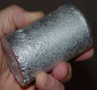
After about two hours of cooling, the frozen cylinder is ready to be stripped from the sand mold, as shown below. Two hours is a long wait, but you don't want to hurry the cooling of the hot casting. Applying water is very dangerous.
Below is the rough-cast cylinder, ready for machining. My castings are getting better with practice on the techniques of creating molds. This one isn't perfect on the surface, but the dimensions are correct, meeting all the requirements for the machining steps which will follow.
The rough casting needs a little hand filing to remove some bumps and make the outside ready for the 3-jaw chuck on the lathe.
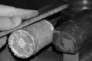
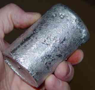
After dressing, shown below, the cylinder is ready to be chucked in the lathe and finished.
(Work on the further steps below is yet to be completed. I will describe the plans.)
The rough casting is trued on the lathe, and turned down to the final OD of the bore. A center hole on the top edge is drilled and tapped, for optional fixed mounting on the press hardware.
The cylinder will be in two halves, split along the vertical axis, to permit easy separation from the pressed grain. This will require casting two rough halves with slightly extended edges, which then are face-milled to have planar mating edge surfaces.
The rough cylinder halves will begin as cast pieces, using my coffee-can foundry to melt scrap aluminum, which will be poured into a sand mold. The open C-shape of each cylinder half permits using an open mold, which is appropriate since I have not yet attempted the more advanced cope-and-drag molding. A wood model to form the molds will be turned and sawed from a fine-grained wood, with a splint glued on to extend the cut edge for a milling allowance.
The two halves of the rough casting are mated along the milled edges with hose clamps into a unit, mounted in the 3-jaw chuck of the lathe, and turned on the lathe for an inside bore, outside diameter, and faced end. The cylinder is reversed end-for-end on the chuck, adjusted to zero runout, and finished likewise on the other end. This yields a precisely bored cylinder in two precisely mating halves.
The precision of the cylinder split with respect to the center axis is determined by how the lathe chuck clamps onto the rough casting. This clamping position can be precisely fitted by milling flats onto the outside of the rough casting, after the edge flats are milled, using the edges as a reference. One such flat is milled parallel and opposite to the edge facing. The other two will be at 60 degree angles (milled on an angle vise) to the opposite edge flat.
The sleeve is a simple bored cylinder which mates to the outside diameter of the cylinder halves.
The base center is drilled to receive a 1/4 in insert. The petaled insert with 1/4-inch projection is machined from 3/4-inch rod. A dowel filler is machined to fill the insert hole when no insert is to be used.