An Optical Prototyping System
Updated as of March, 2014.
First published on May, 2006.
Description
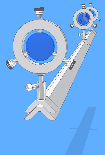 This is a CAD model of an inexpensive optical prototyping ("optical breadboarding") system which I
developed for my optical engineering laboratory. The optical rail is shop-made from inexpensive standard structural aluminum angle
(in the size 1.5 x 1.5 x 1/4 inches).
Both the base rail and the mating component carriers are made from the same aluminum stock, which nest to each
other using a dovetail principle, yielding a surpisingly good degree of precise alignment.
The extruded aluminum stock is also surprisingly straight, square, and rigid as supplied without any additional machining.
Many other components are just hardware store items. The only machining steps are (1) milling the
corner of the aluminum angle to relieve enough material to permit nesting, which I perform on the Bridgeport milling machine, and
(2) cutting and drilling/tapping "donuts" from aluminum or polymer thickwall tubing for lens mounts, which I perform on one of my larger lathes.
This is a CAD model of an inexpensive optical prototyping ("optical breadboarding") system which I
developed for my optical engineering laboratory. The optical rail is shop-made from inexpensive standard structural aluminum angle
(in the size 1.5 x 1.5 x 1/4 inches).
Both the base rail and the mating component carriers are made from the same aluminum stock, which nest to each
other using a dovetail principle, yielding a surpisingly good degree of precise alignment.
The extruded aluminum stock is also surprisingly straight, square, and rigid as supplied without any additional machining.
Many other components are just hardware store items. The only machining steps are (1) milling the
corner of the aluminum angle to relieve enough material to permit nesting, which I perform on the Bridgeport milling machine, and
(2) cutting and drilling/tapping "donuts" from aluminum or polymer thickwall tubing for lens mounts, which I perform on one of my larger lathes.
If this modified aluminum angle (that is, already milled flat on top) were supplied as the basic component, the user can then
use hand tools to cut this stock to fit his requirements for railing and component bases.
The lens holder stems may be as simple as 1/4-20 threaded rod and nuts.
Shown are more versatile stems consisting of a threaded post and telescoping stud which are each machined from 1/2-inch round aluminum.
The nylon thumbscrews are an inexpensive stock item
from mscdirect.com.
The posts or threaded rods and thumbscrews allow adjustments for precision aligment.
O-rings or rubber bands can clamp the dovetail mounts to the railing.
Of course, other mounting components for light sources, irises, targets, rail feet, etc., are needed.
Systems based on a dovetail or box-beam shape perform better, but are quite a bit more costly.
How to Photograph Laser Beams
 Here's is an example of the rail in action, and a demonstration of the dodged-beam technique for photographing laser beams.
Behind your point of a view, to the left, is a laser beam expander and collimator.
This uses an ordinary red laser sight for a Weaver mount, which conveniently provides
an on-off switch and a mounting dovetail to attach it to the rail pedestal. The narrow beam is expanded into a cone by a small positive lens scrounged
from an old hand-held document scanner, the lens being mounted in a small attachment fitted to the Air Shot in the machine shop.
This spreading cone of laser light is then captured and collimated to a broad beam by a larger achromat lens (40mm dia x 120mm fl),
yielding a 40mm diameter expanded beam.
The laser and expander take up about 30cm of the length of the 1.3m rail, leaving
about a full meter of room to experiment with lenses. Over this length, the collimated beam is very nearly
a cylinder of parallel laser light rays, as if the beam had arrived from an infinity source, although there
is necessarily a small degree of beam waisting.
In the photo, another 40mm diameter achromat lens is shown focusing the expanded
beam onto a target component. This apparatus is stationed at the opposite end of the rail from the collimator source.
This demonstrates one application of the rail and collimator, which is to measure the focal length of an unknown lens.
To photograph the beam, the scene is set up, and the digital camera mounted on a tripod and framed for the shot.
The camera, in manual aperture/exposure mode, is set to a low ISO speed and small aperture, and a 30 second time
exposure. The shutter delay is used to open the exposure, and holding a white card in your hand, you sweep the card
("dodge") along the beam path. This obtains a picture of the beam without the use of fog, smoke, or dust, which are
the last things you want contaminating an optical laboratory.
Rather than sweeping the card, you can also dodge the card edgewise in and out the beam quickly, along intervals on
the beam path. This will yield a series of planar cross-sections of the beam, which can help to visually demonstrate or document
ray paths.
By blocking the expanded beam at the collimator lens with a card having two or three large pinholes, you can obtain
several collimated beams from a single laser. These are necessarily dim, but are brought out well by the dodged time-exposure
technique.
Another trick I serendipitously discovered for visualizing the laser rays is to interpose a bottle of Fantastik brand "Orange Action" all-purpose
cleaner. The orange dye in this product has a peculiar ability to luminously disperse the laser light as it passes through liquid.
And it doesn't spoil like a milky emulsion usually suggested for this purpose.
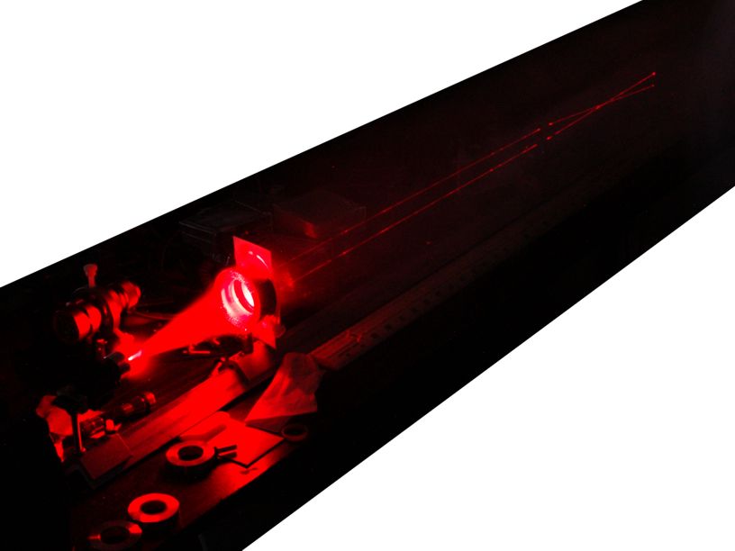 This photo shows the pinhole technique for getting multiple collimated beams from one laser,
which then can be visualized with a white card directly or with time-exposure dodging.
This photo shows the pinhole technique for getting multiple collimated beams from one laser,
which then can be visualized with a white card directly or with time-exposure dodging.
How to Photograph and Measure Ordinary Light Beams
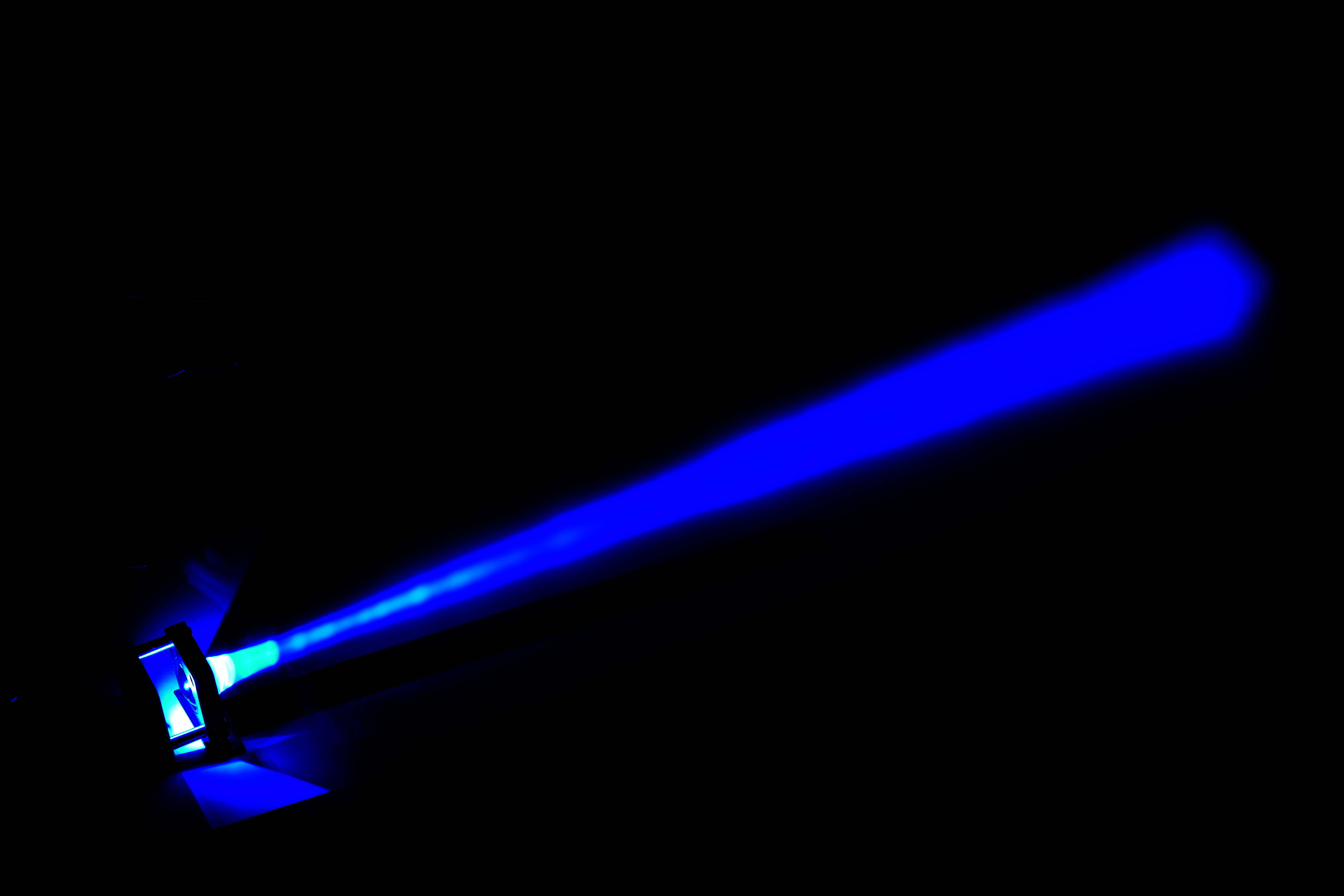 The light-dodging photography technique works just as well for ordinary light beams as for laser beams.
For example, at left is a photograph displaying the beam output by a blue LED and condenser I designed for retinal photography.
This was a single time exposure where I swept the beam with a handheld white card.
The light-dodging photography technique works just as well for ordinary light beams as for laser beams.
For example, at left is a photograph displaying the beam output by a blue LED and condenser I designed for retinal photography.
This was a single time exposure where I swept the beam with a handheld white card.
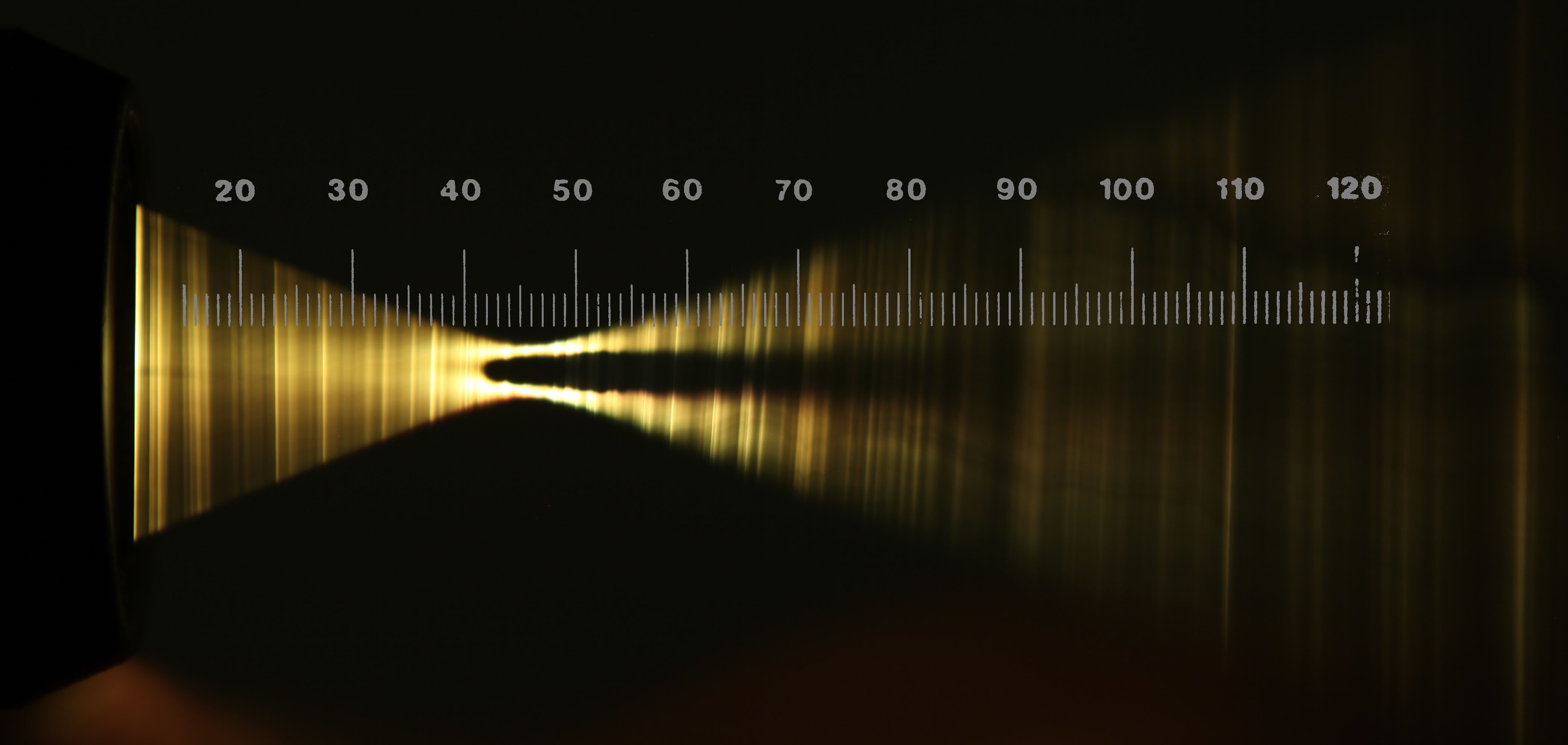 Here is a different technique for beam photography on the same principle, but instead of a white card I swept a thin white thread (dental floss!) held taut
between my hands along a vertical slice of the peculiarly shaped beam produced by a retinal camera instrument.
This shows the shape of the light bundles emitted by the instrument into the eye.
The instrument is at the left, with the light passing out of the instrument from left to right.
The pupil of the subject eye would be held at about the 45mm distance, where
the wide angle of illumination narrows to a waist with a dark center,
such that rays of light travel into the eye through only the edge of the pupil. These rays then spread out again, illuminating a wide field of the eye's retina.
The camera simultaneously photographs the
retina by looking only through the dark center of pupil. Since the light enters the pupil only at the edges, and does not fall on the center of the pupil,
there is no reflection at the cornea of the illumination source, which otherwise would wash out the camera's view of the retina.
Here is a different technique for beam photography on the same principle, but instead of a white card I swept a thin white thread (dental floss!) held taut
between my hands along a vertical slice of the peculiarly shaped beam produced by a retinal camera instrument.
This shows the shape of the light bundles emitted by the instrument into the eye.
The instrument is at the left, with the light passing out of the instrument from left to right.
The pupil of the subject eye would be held at about the 45mm distance, where
the wide angle of illumination narrows to a waist with a dark center,
such that rays of light travel into the eye through only the edge of the pupil. These rays then spread out again, illuminating a wide field of the eye's retina.
The camera simultaneously photographs the
retina by looking only through the dark center of pupil. Since the light enters the pupil only at the edges, and does not fall on the center of the pupil,
there is no reflection at the cornea of the illumination source, which otherwise would wash out the camera's view of the retina.
I composed this photograph from two photos using a special telecentric DSLR lens I constructed from a Melles Griot 59LGH416 telecentric gaging lens attachment.
The telecentric principle provides a precise metrological calibration to the pixels of the digital camera, which then give a precise
scale to physical measurement, with flatness, linearity, and independence from distance to the camera.
By similarly photographing a precision ruler, and superimposing that ruler image onto the scene with
Photoshop, one achives a precise measurement of the scenery subjects. Hence in this case, we could not only view, but precisely measure the geometry of the illumination
beam to tenths of a millimeter.
Thine eye diffused a quickening ray.
I woke, the dungeon flamed with light.
-- Charles Wesley, Psalms and Hymns, 1738
|
Have a comment or question about optical prototyping or beam photography?
Email me at:
kinch@truetex.com
Richard J. Kinch
Back to Microscope Digital Camera Adapters page
Back to Machine Shop page
Back to Home page