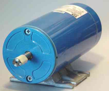
Figure 1. Pacific Scientific 1/3 HP PMDC motor, before servo modification. This is a hefty motor, over 1 foot long, weighing 20 lbs.
Although I experimented with dozens of different stepper motors and more than a few stepper controllers, I came to understand that servomotors are a much better approach to motion control for the X-Y table on the mill-drill.
What's wrong with steppers?Steppers are appealing because they seem cheap compared to servos. But the price advantage only works for small torque and speed requirements. If you analyze the demands of moving a large X-Y table with desirable velocity and force, servos can do a better job for about the same price. My stepper motor experiments started out with the notion that I could build my own inexpensive stepper controllers with a few transistors, which I was able to achieve. However, the simple stepper controllers cannot run a large motor, and cannot run any motor faster than a few 100 rpm. The sophisticated controllers that achieve higher stepping speeds (1000 rpm or more) and torque are so costly that they don't compete with the cheaper servo controllers. If you add the cost of encoder feedback to guard against lost steps, you wind up with a still more expensive system.
I discovered that relatively recent innovations make servo motors cheaper than ever, especially if you are capable of some improvisations of your own. These innovations are (1) inexpensive step-and-direction servo controllers from Geckodrive, and (2) inexpensive quadrature encoders from Agilent and Renco, which can be used to retrofit an ordinary motor to servo duty.
The Geckodrive controller I use is the G320, which is designed to control a permanent-magnet DC (PMDC) servomotor having a quadrature encoder. While such servomotors are expensive, it is possible to convert an ordinary DC motor into a servo by the addition of a rear shaft and encoder. There is some precise drilling involved, but this requires only an ordinary drill press or a mill-drill.
Figures 1 and 2 show a 1/3 HP PMDC motor from Pacific Scientific. Such motors list for about $200 to $300. They are typically used with with a pulse-width speed controller for applications like running conveyer belts that require good torque at all speeds. PMDC motors from 1/4 HP or so up to a few horsepower in size are typically standardized to run at a nominal 90 or 180 VDC. These are rather high voltages for electronic drives, but the trade-off is that the current requirements are much lower. This motor has a nominal 3.2 amp current draw, but this is for continuous duty; we'll analyze below how in use the current may peak at around 20 amps.
This particular motor has a 3" shaft height, which corresponds to the so-called NEMA 48T frame size (48 being the number of 1/16" of shaft height, and "T" indicating the 1960s revision of the NEMA standard, which is still current). The body is 4.5" diameter by 10" long, and the shaft is 5/8" with a 3/16B key slot, projecting 2" from the face. The weight is about 20 lbs, a hefty item. I removed the cast foot mounting and used the faceplate screws to attach the face to the mounting bracket; I would have preferred to have a bolt-circle style faceplate, but this was all I had available cheaply (ridiculously cheap, in fact) from surplus sources. One of the keys to improvising inexpensive solutions is the ability to modify things to fit that ordinarily don't fit.
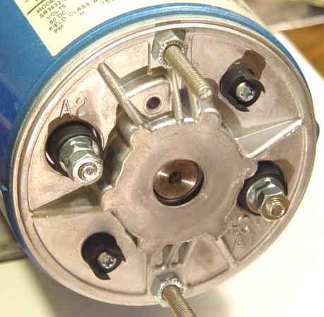
To add an encoder to the motor, one needs a rear shaft extension with a diameter to match the encoder wheel, typically 1/4". While some motors have such an extension by design, I had to add it to this surplus unit. Figure 3 shows the end of the 5/8" shaft of the motor, into which I have drilled a 1/4" hole. Based on the dimensions of a 2" Renco encoder, which requires a 0.65" to 0.74" shaft projection, the hole is drilled 0.570" deep into the shaft. This drilling depth is chosen to yield about 0.5" of depth into the shaft proper, since the end of the shaft is recessed slightly inside the motor end housing. The length of the encoder shaft projection should be 0.74", and thus the drill rod length is 1.31". The Agilent encoders use a slightly shorter extension, but can accommodate the longer one. And it is easier to shorten the projection after it is installed, versus putting metal back!
For the body of the encoder, Renco specifies two 4-40 UNC threaded mounting holes 0.2" deep on a 1.812 bolt circle, for both the RM21 (2.1 inch overall diameter) and RM15 (1.5 inch overall diameter) encoders. These holes must be drilled and tapped into the motor end frame. Agilent encoders accept an optional mounting adapter for this same configuration. If the motor end frame will not accept these holes, then one would have to fabricate an adapter plate and use a longer encoder shaft. The smaller Renco RM15 encoder also can use 2-56 UNC holes 0.2" deep on a 1.28" bolt circle.
The hole must be accurately sized, and accurately centered and aligned on the shaft axis, or else the shaft extension will have runout or wobble beyond what the encoder can tolerate. So to drill this hole, I stood the motor on its face, placing the 5/8" shaft in a UHMW (polyethylene plastic) scrap block into which was drilled a matching 5/8" hole (using an 5/8" end mill to get a square, flat bottom). This plastic block was clamped on the mill-drill table and its hole centered accurately below the spindle. With a 1/4" drill bit chucked in the mill-drill spindle, I ran the motor such that the shaft turned in the (self-lubricating) UHMW block. A critical fact about the motor shaft is that it is originally manufactured by turning on a lathe using a live center, so that it has centered dimple on its tail end. Now we can center the drill bit on this dimple in the spinning motor shaft, boring a precisely centered hole, much like the technique of drilling a center hole with a lathe tailstock. The mill-drill spindle and the drill bit, except for downward travel, remains stationary. I suppose it would also be possible to chuck the whole rotor (or even the whole motor) in a lathe (but my minilathe isn't long enough for that) with some method of steadying the tail end (such as a steady rest) for center drilling there.
To remove swarf from the motor bearing and interior, I had to disassemble the end plate and commutator brush assembly and clean them . The recessed design of the rear shaft end and bearing would not permit catching the swarf during drilling. Two 12" long screws pass from the faceplate, all the way through the body of the motor, and out the rear plate, and hold the two plates to the cylindrical body of the motor. The very strong permanent magnets in the body of the motor extert a strong pull on the loose rotor, so slide a tube of mylar (PET plastic) sheet or heavy paper around the rotor when removing or inserting it, to prevent damage to the rotor or the brittle magnets. I made a sleeve from 0.010" PET plastic sheet (cutting up a 2-liter soda bottle would supply a similar material) taped around the rotor. Carefully pick out any bits of debris loose in the motor before reassembling. The brushes are spring loaded and require some manipulation with a probe to reassemble over the rotor bearing and commutator.
Knowledgeable machinists will have already surmised that a 1/4" drill bit will drill a slightly oversize hole. The drill rod will not fit snugly, but loose and wobbly in the new shaft hole. This is accommodated by my method of gluing and truing the shaft extension into the hole; indeed, some gap is necessary to provide a proper bond for the cyanoacrylate glue. The drill-rod piece is cut to length based on the projection needed for the encoder. The shaft hole is cleaned with a Q-tip and naphtha in preparation for a good glue bond. With the tail end of the motor up, a drop of cyanoacrylate glue (Super Glue) is drizzled into the hole, being careful not to contaminate the bearing area with spilled glue, and the drill-rod is then inserted. The rod is then removed and another drop of glue added, until the glue rises to just ooze a fillet above the end of the rotor shaft. While the glue is still an unpolymerized liquid, run the motor at a few revolutions/second, and as the glue firms up, nudge the spinning drill rod so as to remove the runout and wobble as best you can estimate by visual inspection. When the glue has set enough to hold the drill rod in position, but not yet fully set, finalize the alignment with gentle nudges, and then either wait for the glue to fully set, or apply a glue accelerator. The visual inspection and truing of the spinning shaft extension is well within the runout requirements of the encoder. The glue bond is quite strong, and the encoder wheel spins freely on it, so the arrangement should be entirely durable.
An improved method for bonding the encoder shaft is to knurl the portion of it that will be captured in the motor shaft. With proper oversizing of the hole, one can produce a tight fit that needs no glue. Knurling typically raises about 0.005" (more or less, depending on the force applied) of additional diameter, which can just fill the oversize of a good 1/4 inch drill bit. Knurling is best done using a knurling tool on a lathe, but can also be done with only a drill press and vise if you have the scissor-pinch style of knurler.
The accurately-ground 0.250" drill rod is a few 0.001" too large to fit easily through the encoder wheel; the projecting portion of the rod must be ground down to be slightly undersized. After the glue is fully set, with the motor again under power, use a flat file in hand to shave off a bit of shaft diameter, until a trial fit of the encoder wheel is unencumbered. Polish the rough-filed surface with a bit of fine sandcloth. One might do this undersizing on the lathe before gluing in the piece, but cutting it down in the final position allows you to correct a few thousandths of any remaining runout.
Grind a slight flat area on the side of the shaft extension to receive the setscrew from the encoder wheel. Without this flat, the burr raised on the shaft from tightening the setscrew against it makes later removal of the fragile encoder wheel impossible without ruining the wheel. It is important to have the clearance to remove and reinstall the encoder, since disassembly is required if the motor ever needs a repair or brush replacement, or if you ever want to reuse the costly encoder on a different motor. Renco recommends only 20 oz-in of torque on the setscrew, and warns that overtightening will cause brinelling of the shaft.
Encoder mounting is relatively simple with the completed shaft extension. Drill and tap threaded holes for the encoder mounting. The alignment of the encoder depends on the correct placement of these holes, so they must be accurately placed. Before drilling out the rotor dimple, I used compass points and a straightedge to accurately scribe the centers of the hole locations, and a punch to dimple these locations for accurate centering of the drill. Standard spacing is a 46mm diameter circle with #4-40 screws or the next smallest metric screw. A good-quality tap is called for in this threading task, so as to avoid ruining the end plate (although one could repeat the holes at other angles if need be if the first try failed).
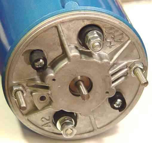
I didn't happen to have the correct electronic connector for this Agilent encoder, so I improvised with some 0.1" header pin receptacles and heat-shrink tubing. Since this assembly is subject to a lot of vibration (being coupled to the mill base), it requires durable electronic construction parts and techniques. You can also see that I have adapted the (+) and (-) motor power screw lugs with 1/4" spade lugs, for an easy disconnect.
A number of factors with complex interactions govern the performance of a system of this type: torque, speed, acceleration, power supply cost. Performance analysis is critical in achieving a satisfactory design and implementation. Guessing about motor sizes, or using rules-of-thumb you might have heard, will likely result in machinery that is too slow, loses servo lock from lack of torque, or that is over-designed and over-priced.
The horsepower rating of a DC motor leads directly to a good estimate of continuous torque. The HP rating of a PMDC motor indicates the continuous output at rated speed, which is limited by heat dissipation and/or electrical insulation breakdown. Bursts of considerably more power and/or torque are available for short periods, which is well-matched to the start-stop characteristics of CNC motion.
Of primary interest is the torque available to overcome table stiction-friction and the mechanical inefficiency of the table screws, yet still move the work into a forcefully reacting tool. The G320 controller tolerates a maximum of 128 steps deviation before losing servo lock and shutting down. With 2000 PPR encoders, this amounts to a maximum positioning error of 128/2000 rev * 0.1"/rev = 0.006". The 1/2000 rev step accuracy is vastly smaller than the other positional errors in the system (screw non-linearity, backlash). In practice we would insist on a much stiffer system holding dynamic error to 0.001" or so. This "stiffness" comes from tuning the software step rates to be well below the maximum torque and speed available from the system. The motor may be rated for 1750 rpm, but it is not "controllable" at that speed, since "control" implies that you can briefly run somewhat faster to maintain servo lock; thus we must configure the software for a maximum step rate targeting a significant lower top speed.
A little physics and algebra, given that 1 HP = 550 ft-lb/sec, leads to the formula for motor shaft torque as a function of horsepower and rotational speed:
torque [oz-in] = HP / rotation [rpm] * 10^6
Which for the Pacific Scientific motor above yields:
Continuous torque = 0.33 / 1750 * 10^6 = 189 oz-in
The stall torque is conservatively 6 times this figure, or over 1000 oz-in (!). DC motors deliver torque proportional to current, so we can likewise expect the peak current demand at up to 6 times the continuous rating of 3.2 amps, or almost 20 amps, which is conveniently the maximum output of the Geckodrive G320, and which must be available from the power supply.
In one revolution, a 1" radius traverses 2 * pi = 6.28", while the table moves 0.1". Thus the mechanical advantage of the screws is about 63:1 in converting rotational torque to linear force. Thus our 1000 oz-in peak torque is multiplied to a linear force of 63000 ounces, or about 2 tons. The 50 percent efficient acme screws, versus ballscrews at 90 or 95 percent mechanical efficiency, cut this force to about 1 ton. This is still a good target for linear table force in common milling applications.
DC motors deliver speed proportional to voltage, in this case up to 1750 rpm (no load) at 90 VDC. The G320 drive is restricted to a maximum of 80 VDC, so we cannot quite reach that maximum. To maximize performance given the limits of all the components, we will need a power supply capable of delivering 80 VDC at 20 amps. While this would seem to imply a hefty 1600 watts output just for this one axis motor, in practice high currents are only demanded at slower speeds, since the higher speeds are applied for rapid traversal only and not for cutting.
A simple unregulated DC supply consisting of a variable autotransformer ("Variac") rectified by a full-wave bridge rectifier and filtered by a 1000 ufd or so capacitor is quite effective at delivering the necessary power. Autotransformers have a deep "gutsy" ability to deliver 10 times their continuous current for short periods, with a very low impedance that prevents significant voltage sag. The chopped and sampled output of the digitial servo controllers also compensates well for any unregulated or rippled power. Appropriate wiring and insulation is important, since autotransformer output voltages are referenced to the AC line neutral.
Note that the Geckodrives must have an isolated power supply, since their cases are live with respect to the power supply. Thus if you are going to use an autotransformer, you must precede it with an isolation transformer. You could just use a toroid transformer that rectifies to the 80 volts DC of the Geckodrives (80/sqrt(2) = 56 volts AC) without the autotransformer, but they are rare. Instead, you can use a range of beefy toroid transformers that are likely to be cheap on eBay, and use the autotransformer to adjust to the output to something just under 80 volts DC.
If the power supply is limited in either voltage and/or current, suitable limits must be applied in the tuning parameters of the CNC software step rates, lest the servo lock fall behind.
The drive system must also be capable of absorbing a similar amount of power during decelerations, especially if ballscrews are minimizing frictional losses. Since the rated speed of 1750 rpm is at 90 VDC, at 80 VDC the speed will be limited to about 80 / 90 * 1750, or 1555 rpm.
One also must hold some available motor rpm in reserve in the CNC software tuning. The motor needs "headroom" of potential speed well above what the software might demand, in order to reliably maintain servo lock in catch-up situations. The magnitude of this "headroom" will also determine the tracking error between the targeted and actual table position. Thus we might set the maximum step rate in the CNC software to 1/2 or 2/3 of the maximum 1555 rpm available, or about 800 to 1000 rpm. With 0.1" of linear motion per turn on the Acme screws, this yields a maximum practical slew speed of about 80 to 100 inches per minute. While such speeds are not in an industrial class of performance, such as CNC machining centers that typically deliver 500 to 1000 inches/minute rapid traversal, this is still very respectable for an inexpensive small machine conversion. Indeed, one might spend many $100s for an high-quality table power feed that delivered a top slew rate of 90 inches/minute.
One sees the advantage of ballscrews, both in economy and performance, in this kind of performance analysis. Ballscrews are costly, but usually justified as a no-backlash transport mechanism that permits accurate circular interpolation under CNC control, versus Acme screws that have significant backlash and thus significantly limit the types of patterns that can be cut. But an additional advantage to ballscrews is their mechanical efficiency of 90 or 95 percent versus 50 percent for Acme screws. Ballscrews deliver almost all the torque from the motor to the table, while Acme screws waste around half of it in friction. This means that if we replace the 0.1" pitch Acme screws with 0.2" pitch ballscrews, that the torque requirements are about unchanged, even though the linear motion is doubled! In this case, that would double the slew rate to 160 or 200 inches/minute, which is the kind of performance formerly known in costly high-end CNC equipment. Alternatively, one could interpret this as the "cheaper" Acme screws requiring twice as much motor and power supply capacity (at a disproportionate extra cost) for any given performance, which is to say, perhaps not really "cheaper".
One significant performance compromise in converting a big DC motor like this to a servomotor is that the inertial characteristics of the rotor design are not optimized for quick starts and stops. The rotor is big and heavy, being more optimized to deliver efficient power at steady speeds, rather than being able to rapidly change speeds. In physical terms, the acceleration rate of this improvised servomotor is much less than an optimized servomotor design of the same continuous power output. This is somewhat compensated for by the fact that no gearing is needed for this monster motor to meet the torque requirements (gear ratios proportionately decrease acceleration as well as speed). Another compensation is that in the CNC milling application, much of the time the table is moving at a constant slow velocity, rather than jumping around between work locations, although this of course depends on the type of work being done. And the happiest compensation is that the cost of the motor is 1/10 of a servo-optimized design. But the fact remains, that this motor is rather like a football lineman, rather than a pass receiver; both are capable athletes, but neither performs perfectly at the other's position. In machine design, agility and power are generally conflicting goals.
Of the three types of servomotors, brushed DC motors are the cheapest in the fractional-horsepower capacity. The other two types (brushless DC or AC) require much more expensive controllers, but the absence of brushes makes for less maintenance.