Making Digital Camera Telescope Adapters
As a lad of 13 years age back in 1969, I received as a Christmas present the most
wonderful thing that my young scientific mind had been yearning for: an Edmund
Scientific Company 4-1/4 inch reflecting telescope. For years I had longed
to see the heavens magnified, and now I had the essential instrument. Many were
the nights I spent happily engaged in learning to navigate the heavens, finding
star clusters, planets and their moons, nebulae, and the moon.
One goal I never realized as a youngster was the advanced equipment and
techniques to make amateur astrophotographs with my telescope. The telescope
itself was hardly an affordable expense for my family, because such things
were much more costly in those days, and we were not wealthy enough to
indulge a child in the more serious aspects of my amateur-astronomer
dreams. Photography would have required an SLR camera, an elaborate
mounting system, and perhaps most significantly, lots of expensive film
and processing. So my youthful observations are only distant visual
memories.
Nearly 35 years later today, I find that digital photography and my
machine shop have made my lifelong dreams of astrophotography realizable.
I was able to design and build a camera adapter for my childhood
hobby telescope (which I still have). My 5-megapixel Sony DSC-F707
(F-707) (mechanically equivalent to the Sony DSC-F717) camera now snaps
inexpensive images that exceed the resolution of the telescope optics,
with instant viewing for correction of exposures and alignment.
The occasion that finally motivated me to complete this project was the historical
opposition of the planet Mars in August 2003. This approach was widely reported
in the popular press, as the closest this neighbor has been in 60,000 years.
The disc of Mars presented about 26 seconds of arc, which with the camera zoom
and 150 magnification of the telescope, covered about 120 pixels of diameter.
This was an excellent subject for my situation, since our night skies here in
southeast Florida are washed out by city lights, but good astrophotography is
still possible for the very bright planetary discs.
This was definitely a machining job for CNC methods. It required cutting a
5-inch arc into side of a 1.25-inch aluminum extension rod to fit the outside radius of the telescope tube.
The CNC ability also let me program a tool path to cut a 1.25 inch diameter hole
with radial slots for a round bar clamp on the camera stage.
These circular shapes would have normally required a boring bar, or large (expensive) rotary table,
but I was able to execute them with circular interpolation in software using only an inexpensive end mill.
Although I do not have ballscrews yet installed, the backlash compensation in
TurboCNC was able to cut arcs with acceptably minimal distortions.
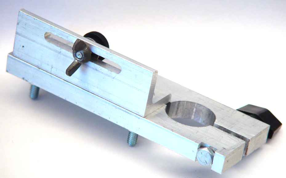 These two photos of the stage show its construction.
I designed the assembly such that the stage moves up and down on the extension rod, and also swivels on it,
while unclamped, and then firmly clamps in place.
I designed the stage such that the camera can move radially, in and out from the extension
rod axis, and also swing across the axis of the focuser.
This provides articulation with 4 degrees of freedom to permit positioning the
camera at a range of distances from the telescope focuser and precisely aligned
in all directions with the focuser axis.
I sized the dimensions to provide a wide range of motion
for what would be needed to align various cameras, not just my current camera.
The rather heavy aluminum stock used provides good stiffness and tight, smooth
bearing and clamping surfaces, yet is light enough to require little counter-balancing
weight on the telescope tube.
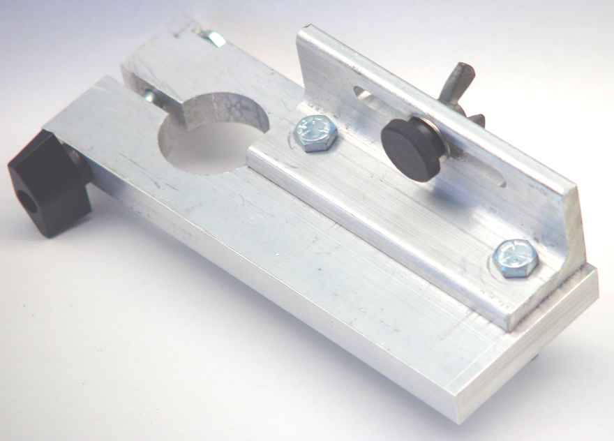
These two photos of the stage show its construction.
I designed the assembly such that the stage moves up and down on the extension rod, and also swivels on it,
while unclamped, and then firmly clamps in place.
I designed the stage such that the camera can move radially, in and out from the extension
rod axis, and also swing across the axis of the focuser.
This provides articulation with 4 degrees of freedom to permit positioning the
camera at a range of distances from the telescope focuser and precisely aligned
in all directions with the focuser axis.
I sized the dimensions to provide a wide range of motion
for what would be needed to align various cameras, not just my current camera.
The rather heavy aluminum stock used provides good stiffness and tight, smooth
bearing and clamping surfaces, yet is light enough to require little counter-balancing
weight on the telescope tube.
|
 The main portion of the stage is a 2-1/4" x 6-1/4" rectangle of 1/2" thick aluminum
6061 alloy. Into this is machined a 1-1/4" hole to receive the extension rod.
A 3/16" channel is milled from the edge, across the hole, and 1" further into
the stock, which turns the material around the hole into clamping arms.
Clamping force to the extension rod is provided by a 1/4"-20 x 2.5" hex head screw, with a thumb nut.
The hex head rests in a 7/16" channel, milled to lock the screw.
A 4" length of 1-1/4"-3/16" aluminum angle is bolted to the stage to provide a broad, planar
surface for clamping the camera via the tripod mount. A 1/4"-20 x 1/2" thumb screw
engages the tripod mount on the camera, and a wing-nut acts as a keeper for the thumb screw
when the camera is unmounted.
The main portion of the stage is a 2-1/4" x 6-1/4" rectangle of 1/2" thick aluminum
6061 alloy. Into this is machined a 1-1/4" hole to receive the extension rod.
A 3/16" channel is milled from the edge, across the hole, and 1" further into
the stock, which turns the material around the hole into clamping arms.
Clamping force to the extension rod is provided by a 1/4"-20 x 2.5" hex head screw, with a thumb nut.
The hex head rests in a 7/16" channel, milled to lock the screw.
A 4" length of 1-1/4"-3/16" aluminum angle is bolted to the stage to provide a broad, planar
surface for clamping the camera via the tripod mount. A 1/4"-20 x 1/2" thumb screw
engages the tripod mount on the camera, and a wing-nut acts as a keeper for the thumb screw
when the camera is unmounted.
|
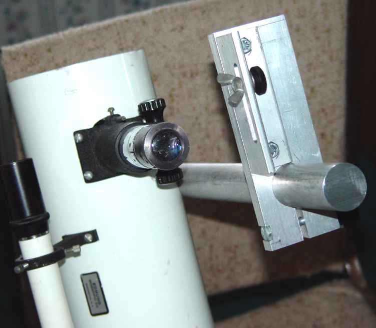 This photo shows the assembly mounted to the telescope tube, without the camera.
|
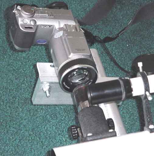 This photo shows the assembly with the Sony DSC-F707 camera mounted.
As noted, the range of adjustment is such that just about any camera with a standard
tripod mount can be mounted to this stage and properly aligned with the focuser.
This photo shows the assembly with the Sony DSC-F707 camera mounted.
As noted, the range of adjustment is such that just about any camera with a standard
tripod mount can be mounted to this stage and properly aligned with the focuser.
|
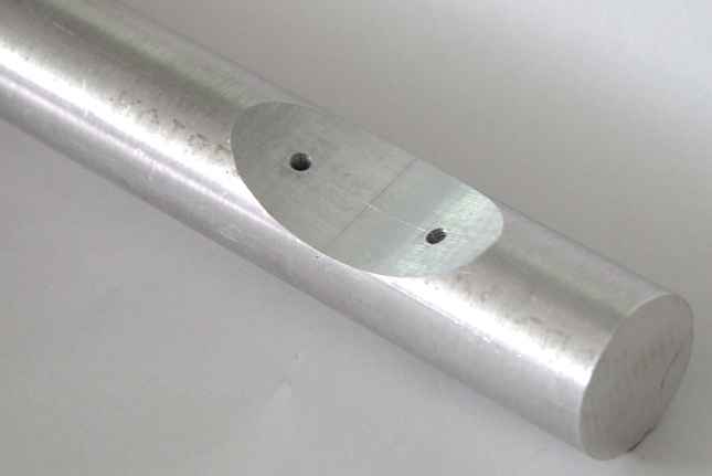 This photo shows the circular arc CNC-machined into the side of the rod.
The trigonometric calculations are a bit involved, but the result is a saddle-shaped
oval about 2-1/4" long by 1-1/16" wide, cutting a maximum of about 3/8" deep into the 1-1/4" diameter cylindrical rod.
You can see the holes drilled and tapped for two 10-32 x 1/2" hex-head cap screws which attach the rod
to the telescope tube.
These holes are drilled at angles to project radially from the axis of the scope tube.
The layout of these holes inside the curve is best determined by first scribing the axes of alignment,
and then transferring a paper tracing from the scope tube and
applying a spring-loaded center punch through the paper.
This photo shows the circular arc CNC-machined into the side of the rod.
The trigonometric calculations are a bit involved, but the result is a saddle-shaped
oval about 2-1/4" long by 1-1/16" wide, cutting a maximum of about 3/8" deep into the 1-1/4" diameter cylindrical rod.
You can see the holes drilled and tapped for two 10-32 x 1/2" hex-head cap screws which attach the rod
to the telescope tube.
These holes are drilled at angles to project radially from the axis of the scope tube.
The layout of these holes inside the curve is best determined by first scribing the axes of alignment,
and then transferring a paper tracing from the scope tube and
applying a spring-loaded center punch through the paper.
To assemble the extension rod to the scope tube, the cap screws must be manipulated by hand from inside the
scope, such that they pass through the scope tube holes and engage the extension bar,
turned until hand-tight, and finally tightened with a short 9/64" hex wrench.
This requires care, since the front-surface diagonal optics are close by, and there is
hardly room for your hand. Of course, this procedure is applied with the scope tipped down,
so that a dropped screw or tool does not fall on the primary mirror!
I seem to recall that in the 1960s that Edmund Scientific Co. sold a cast-and-machined bracket
to fit this scope tube, with a spindly extension rod and camera stage.
This was probably somewhat lighter than my assembly, but not nearly as rigid.
|
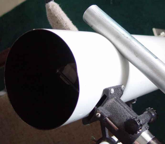 This last assembly photo shows the extension rod attached to the telescope tube.
The circular fit is very close.
The mounting holes on the tube are a bit larger than the screws, so some
wiggle is possible unless the screws are very tight.
This can be firmed up by inserting a thin rubber shim (temporary) or
cyanoacrylate glue (semi-permanent) between the mating surfaces of the rod and tube.
This last assembly photo shows the extension rod attached to the telescope tube.
The circular fit is very close.
The mounting holes on the tube are a bit larger than the screws, so some
wiggle is possible unless the screws are very tight.
This can be firmed up by inserting a thin rubber shim (temporary) or
cyanoacrylate glue (semi-permanent) between the mating surfaces of the rod and tube.
|
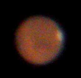
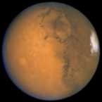
Here are two of the better photographs I was able to snap of Mars in
opposition, and a third photograph taken by the Hubble telescope the same
week. You can see the South polar ice cap at about 2 o'clock
orientation, and some darker regions around the center of the disc.
Considering the modest telescope I used, these are remarkable pictures.
The Hubble picture was taken at a different time of the Martian day, so the dark and
light regions of the surface don't quite match up to mine, but it is interesting to
compare and see that some surface features are vaguely visible with such a
small telescope. In this case, the photos look better than the live visual image,
since you can better control the contrast, brightness, and other processing issues.
The colors in my image are adjusted to be the actual colors in the scope view, at
least as rendered on my current CRT display monitor.
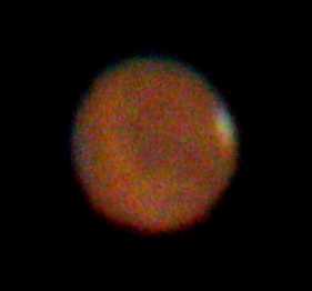
If you compare my two images, the discs are a bit oblong due to some shaking
of the telescope mount, and due to the lack of a clock drive for the 1/30 and 1/6 second exposures
(south being to the right, the smearing of sidereal motion in the image is directed up, and amounts
to about 3 pixels).
This is due my loss some years ago of the original Edmund equatorial mount for
the telescope, which occured when I went to a night launch of the Space Shuttle
and left the mount behind on the very dark Cape Canaveral roadside! (Let me know
if you were the one that found it.)
I despaired of the expense to replace such a mechanism for my vintage telescope,
since the scope has such little value (other than sentimental) these days with
with advent of imported optics, and any money spent would be better applied to a
more advanced unit. Then I conceived of improvising a mount from
a pipefitters vise (which has both a base that swivels and jaws that swivel)
on top of the high-speed grinder pedestal, which together make an alti-azimuth
mount. While the vise "bearings" are crude and difficult to position, it works.
Of course I keep thinking that the machine shop should be put to building a
precision equatorial mount and tracking drive, someday.
Links for Digital Astrophotography
Have a comment or question about my digital camera telescope adapter project?
Want to purchase a custom-made adapter?
Email me at:
kinch@truetex.com
Richard J. Kinch
Back to Machine Shop page
Back to Home page