INSTALLING AND OPERATING THE
DIGITAL CAMERA UPGRADE KITS
for the
TOPCON RETINAL CAMERAS
Models:
TRC-50EX and TRC-50IX
TRC-50X and TRC-50IA
TRC-50VT and TRC-50V
TRC-50F and TRC-50FT
TRC-W and TRC-WT
Richard J Kinch
http://www.truetex.com
January, 2010
This document describes how to install and operate
the digital camera upgrade kits for Topcon TRC-50 series and TRC-W series
retinal cameras. The various adapter models are similar but support variations in the Topcon models according to the following table:
| DIGITAL CAMERA UPGRADE KIT VARIATIONS |
|
Topcon
Model(s)
Supported |
Adapter Kit
Model |
Topcon
Upper Port
Attachment
Mechanism |
Original
Topcon
Electronic
Camera
Synchronization
Interface
Connector |
Upgraded
Digital
Camera
Electronic
Interface
Method |
Digital Cameras
Supported |
|
TRC-50VT
TRC-50V |
EF-TRC-50VT |
M64x1.0
threaded ring |
15-pin D-sub |
Joystick interpolation
with asynchronous flash jumper plug |
All Canon digital SLRs
Nikon digital SLRs with 10-pin remote |
TRC-50F
TRC-50FT |
EF-TRC-50F |
None; rear-port
bayonet only |
None |
Joystick and synchronous flash
internal take-off cable
or pogo connector |
Canon or Nikon full-frame digital SLRs
(Canon 5D or 5D Mark II) |
TRC-50X
TRC-50IA |
EF-TRC-50X-50IA |
M64x1.5
threaded ring |
15-pin D-sub |
Synchronous connection to
upper-port connector;
Optional internal retrofit with upper-port
mirror-synchronization switch |
With mirror-synchronization switch upgrade:
All Canon digital SLRs
Nikon digital SLRs with 10-pin remote
Without switch upgrade:
Canon 40D or 50D only |
TRC-50EX
TRC-50IX |
EF-TRC-50EX |
M63
bayonet |
9-pin D-sub |
Synchronous connection to
base connector |
All Canon digital SLRs
Nikon digital SLRs with 10-pin remote |
TRC-W
TRC-WT |
EF-TRC-W |
M62x0.75
threaded ring |
Manual shutter
release cable |
Manual mirror actuation cable with
adjunct digital shutter control
and synchronous flash |
All Canon digital SLRs
Nikon digital SLRs with 10-pin remote |
| | | | | | |
Note 1: Specify F-mount SLR bayonet when ordering for use with supported Nikon digital SLRs.
Note 2: Rear-port adapters for Topcon TRC-F/FE/JE retinal cameras also available.
|
| | | | |
The following instructions apply generally to all these various adapters, although we will illustrate with the
Topcon TRC-50EX model, unless otherwise indicated.

Figure 1. Digital camera adapter assembly for Topcon TRC-50EX. Shown with typical digital SLR camera body.
This model attaches via the bayonet fitting on the TRC-50EX upper port. Other models attach with a screw ring captured on the adapter tube.

Figure 2. Adapter mounted on Topcon TRC-50EX.
This Topcon model has a fixed viewfinder.
Older Topcon models incorporated a viewfinder into the 35mm film camera back attached to the instrument's rear port;
on such models we will retain the film camera for viewfinding, while photographs will be taken on the upper-port digital camera.

Figure 3. Cross-sectional view of adapter internal structure.
The adapter supplies three different aspects of adaptation: mechanical, optical, and electronic.
The mechanical tube makes the physical connection to the instrument, and holds the camera and optical elements
in the proper orientation and aperture. The optical elements relay and resize the instrument image onto the
digital camera's image sensor. The electronic interface cable forwards the shutter triggering signal from the
instrument to the camera, and in turn the flash synchronization signal from the camera back to the instrument.
Installation instructions:
-
Identify the upgrade kit contents:
Figure 4. Exploded diagram showing adapter components.
(The diagram above is given only to illustrate the adapter principles and construction;
the adapter is supplied fully assembled and ready to use.)
-
Other components you must obtain separately:
- Digital SLR camera from the compatibility list above.
- Memory card(s) for the camera
-
Optional components you may wish to obtain separately:
- Camera AC adapter (if you do not wish to depend on the rechargeable camera battery)
- Computer and software for post-processing and viewing digital photos
- Computer and software for live PC preview as you photograph ("tethering")
-
Familiarize yourself with the digital camera:
If the digital SLR camera is new to you, be sure the learn about the following features which
will be used for retinal photography: On/off switch, mode switch for manual settings, setting manual exposure time,
attaching and removing lenses, remote shutter release connector, flash bracket and hot shoe adapter (Canon Rebels only),
viewing photos on the camera, transferring photos to a computer.
If you will be using a tethering application, you may wish to connect the camera and computer,
and shoot some ordinary photos in tethered mode, to familiarize yourself with the procedure.
-
Topcon TRC-50EX/IX ONLY: Remove and send us the upper port "pogo" connector for modification:
Remove two screws attaching the upper port connector (female "pogo" style) to the instrument.
Store these screws to reuse when the modified connector is returned to you.
Swing the connector up from the instrument body, and observe that the connector is attached
to the instrument via a ribbon cable with plug. Separate the pogo connector from the ribbon
cable by pulling the ribbon cable plug from the socket on the pogo connector.
Send the pogo connector to us for modification, which consists of soldering a 1K ohm resistor
from pins 12 to 19 on the back of the connector.
You can continue to use the TRC-50EX/IX (other than with upper-port accessories) while the connector is removed,
You may also perform this modification yourself if you are capable, rather than sending it to us.
This modification is not required on any Topcon model other than the TRC-50EX/IX.
The modification after installation does not affect use of other upper-port accessories, and may be easily
reverted by clipping off the added resistor.

-
Topcon TRC-50EX/IX ONLY: Reinstall the modified connector:
When you receive the modified connector, install it in the reverse process in which you removed
it: plug the ribbon cable connector into the pogo connector, align the pogo connector onto the
body of the instrument, and fasten with two screws.
The purpose of this modification is to enable the use of an upper-port accessory without having
to provide a connection to the Topcon-proprietary pogo connector. Without this modification,
the TRC-50EX/IX will not switch to use the upper port and digital photos cannot be taken.
The modification does not interfere with the use of other upper-port accessories, and is easily
reversed by removing the resistor if that should ever become necessary.
This modification is not required on any Topcon model other than the TRC-50EX/IX.
-
Topcon TRC-X ONLY: Optional: install the upper-port mirror-synchronization switch:
While the adapter may be used without any internal modifications to the Topcon TRC-50X,
an optional upgrade improves digital camera performance on the TRC-50X, and allows you to use less expensive digital camera models.
Installing this upgrade requires that you (or your instrument technician) remove the TRC-50X cover to mount and solder a switch,
Separate instructions detail the installation of this upgrade.
Without the upgrade, taking a digital photo sometimes requires a second press of the joystick button, and
the Canon model 50D digital camera is required instead of the less expensive Canon Rebel models.
You may have been provided both options with your adapter kit, so that you can use the digital adapter
with or without installing the mirror-synchronization switch.
-
Attach the adapter to the Topcon instrument:
Attach the digital camera adapter to the upper port of the Topcon instrument. This works in the usual way described
in the Topcon documentation for attaching accessories to the upper port, with either a bayonet or screw-ring mechanism.
On the adapter, observe that one end mates to the
Topcon port and the other end to the digital camera lens mount. Insert the Topcon end of the adapter into the
Topcon upper port receptacle, and swivel the locking arm counterclockwise to lock the
adapter onto the instrument (for bayonet mounts) or screw the threaded locking ring down onto the threaded
fitting (for screw-ring mounts).
-
Connect the interface cable to the Canon digital camera:
The interface cable has a split end for the Canon digital camera. The split end terminates in a remote shutter control connector (N3 connector or 2.5mm E3 plug for Canon cameras, depending
on the camera model) and a PC-sync plug. Insert the appropriate connector into the remote shutter release socket on the Canon camera.
For Canon 400D or other Digital Rebel series cameras, attach a hot shoe adapter to the flash bracket
of the Canon camera to provide a PC-sync socket; other Canon models directly provide a separate PC-sync socket
on the camera without requiring a hot shoe adapter. Plug the synchronization cable PC-sync plug into the PC-sync
socket on the Canon camera.
-
Attach the Canon camera to the adapter:
The upper end of the adapter is mechanically a standard Canon EF mount bayonet,
such as is used on Canon EF lenses for the EOS camera series.
(That is, to the Canon camera, the Topcon instrument appears via the adapter to be an elaborate, manual-focus EF lens.)
Attach the Canon camera to the EF lens mount in the usual way, that is, by inserting the bayonet while aligning the red dots
and swiveling the camera. Note that the top of the camera will be facing the operator
when the camera locks into place on the lens bayonet. This makes it possible for the operator
to stand and look into the Canon viewfinder during an exposure.
-
Connect the electronic interface to the Topcon instrument (TRC-50VT models with joystick interpolation connector):
If your kit includes the joystick interpolation cable and asynchronous flash jumper plug, follow the separate instructions
for installing that interface.
-
Topcon TRC-50VT ONLY: Cover the rear-port camera contacts :
Trim a piece of masking tape or the sticky part of 3M Post-It Note to approximately 5mm high by 27mm wide.
Remove the Topcon film camera body from the rear port. Apply this paper to cover the gold camera contacts on the
rear port, as shown in this photo:
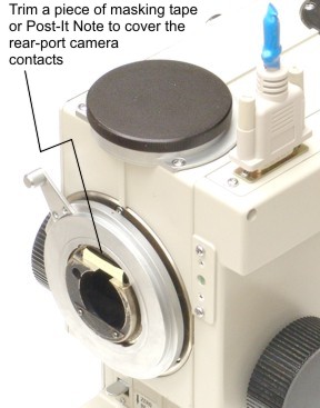
Return the film camera body to the rear port. You will use the original,
superb Topcon viewfinder to frame the digital photos taken by the upper-port adapter and digital camera.
(Should you ever want to revert to film photography using the rear port, you can easily remove this paper cover.)
This covering isolates the film camera from the system, which would interfere with the digital camera.
If the contacts are not isolated with this cover, the flash will not fire for the upper port.
-
Connect the electronic interface to the Topcon instrument (TRC-50 models other than TRC-50VT with direct interface connector):
The instrument end of a TRC-50 synchronization cable terminates in a 9- or 15-pin male D-sub electronic connector. Connect this to the
female connector on the Topcon instrument, found on the left side of the base of the TRC-50EX/IX models,
or near the upper port on all other TRC-50 models. Tighten the screw attachment on the
connector to ensure the connector does not fall off the horizontal connection on the TRC-50EX/IX; other models retain the connector by vertical orientation and snug fit.
Since the cable must run down the side of the TRC-50EX/IX, you may wish to dress it using self-adhesive cable-tie anchor pads.
-
Connect the interface cable to the Topcon instrument (TRC-W and TRC-WT models only):
On the TRC-W and TRC-WT, shutter-flash synchronization is achieved differently than more recent Topcon designs, since the instrument uses a manually-flipped
mirror to switch the mode from eyepiece viewing via the rear port to photographing via the upper port.
The shutter cable assembly we provide in the upgrade kit consists of a hand-held mechanical remote cable having both a manual plunger to actuate
the instrument mirror-flip, and a pushbutton to trigger the digital SLR shutter and flash synchronization.
This cable splits into two opposite ends; the first end terminates in a mechnical plunger tip to actuate the instrument mirror,
and the second end terminates in a remote-shutter electronic connector which mates with the digital camera type specified.
The type of electronic connector supplied on the cable varies with the make and model of the digital camera specified for the adapter kit.
Install the shutter cable assembly on the TRC-W or TRC-WT as follows:
- Screw in the metal plunger tip into the mirror-actuator receptacle located on the bottom of the Topcon rear port.
This receptacle is a silver tube 6mm in diameter which projects down about 12mm.
- Verify that the plunger action flips the mirror firmly and reliably. If the mirror action is sticky or sluggish, it may require
cleaning and lubrication.
- Clean the mirror surface if it is dusty, filmy, fingerprinted, or otherwise contaminated.
This is a first-surface mirror and proper cleaning techniques are critically important.
If the mirror is not clean, photographic images will suffer reduced contrast and definition.
- Insert the electronic connector into the shutter remote socket on the digital camera body.
- Attach the Topcon PC flash sync cord and plug for the upper port to the digital camera PC flash sync socket.
This cord and plug is part of the original instrument; it connects the 3-pin DIN socket on the lower right rear of the flash lamp housing to
the flash sync connector on the old 35mm or Polaroid film cameras.
(Attach the supplied hot-shoe/PC-sync adapter to your camera's hot shoe if it does not provide a PC flash sync socket.)
- Route the loose cables to convenient locations on the instrument.
- Note, there is a small thumbwheel near the plunger actuator which is used to lock and release the mirror-flip actuation.
This thumbwheel rotates into two positions; one position locks the actuation until the thumbwheel is pressed, and another position actuates and
deactuates with the plunger without locking.
You should normally rotate this thumbwheel to not lock the actuation.
To take a digital photograph on the TRC-W or TRC-WT, after acquiring a good view in the film camera viewfinder,
you first depress the plunger on the cable using your thumb in a motion like dispensing a syringe, which mechanically flips the instrument mirror to the upper port.
Second, as the plunger bottoms out from your thumb motion, you simultaneously with the same finger press the push button adjacent to the plunger,
which triggers the digital camera shutter and instrument flash. With a bit of practice you can make a fluid motion which
flips the mirror and exposes the picture with one press of your thumb, and which finishes the exposure before the patient's
blink reflex interrupts the view.
Operating instructions:
-
Adjust instrument for a fixed test subject:
Turn on the retinal camera and set the instrument controls to select the upper port as if using a 35mm camera attachment there,
such as is shown in Photo 3 or 4 below.
Tape a business card or other flat, high-contrast, detailed subject to the patient headrest to serve as a fixed test target.
Frame and focus a view of this target using
the Topcon viewfinder in the normal fashion, perhaps pulling away from the subject and
using the "+" refraction compensation, as for anterior segment views.
Set the retinal camera flash intensity to the lowest possible setting (one or one-half step above "NF" (no-flash)).
-
Adjust Canon camera settings:
Configure the Canon camera as follows:
- Use a fully-charged battery or external AC power supply.
- Power switch: ON
- Mode dial: M (manual)
- Exposure time:
- 1/6 SEC (Topcon TRC-50VT upper-port adapter)
- 1/10 SEC (Topcon TRC-50X upper-port adapter without mirror-synchronization switch upgrade)
- 1/5 SEC (Topcon TRC-50X upper-port adapter with mirror-synchronization switch upgrade)
- 1/30 SEC (all others).
- ISO speed: ISO 100 (or ISO 64 or other lower speed, if available)
-
Topcon models with viewfinder film cameras (TRC-50VT/50V/X/IA) only: attach the film camera for viewfinding.
The viewfinder on the old film camera will be used in the usual way for framing the digital photographs, so the old
35mm film camera back must remain mounted on the rear port of the instrument. Also, the Topcon joystick will not trigger exposures
on the upper-port digital camera without the film camera simultaneously mounted on the rear port, with the film winder turned on.
If the old film camera is not available, this interlock can be defeated by mounting any stock Canon FD-mount device, such
as a macro extension tube, on the rear port. Viewfinding is possible on the upper port with digital SLRs supporting live view,
such as the Canon 40D or 50D, by switching the Topcon instrument to TV mode, although the Topcon instrument must be manually switched back to
the upper-port still-camera mode (such as "upper" on the 50VT, or "35 mm" on the 50EX) to take photographs.
-
Take test subject exposures:
Focus and align on the test subject using the instrument viewfinder in the usual way.
Press the joystick button to trigger an exposure.
At the moment of exposure, listen for the Canon camera mirror flip and shutter mechanisms operating,
along with the Topcon mirror flipping.
Observe the light of the retinal camera flash on the subject.
Immediately after the exposure, the Canon camera should momentarily display a view of the image on the
rear display. Use the Canon menu buttons to review exposures.
Zoom in when reviewing images to verify that the masked edge of the Topcon image is sharply in focus.
Verify that the image of the test subject is also in focus.
Note that the full resolution of the digital camera is much finer than the instrument resolution, so
the highest-resolution images may not appear in focus when zoomed in completely.
-
Take live subject exposures:
It is most convenient to obtain a cooperative, well-dilated colleague or patient for your first live retinal digital image tests.
Collimate and focus on the retina in the usual way with the viewfinder, using the joystick button
to take exposures. Check the images for exposure brightness and adjust the flash intensity to
compensate; the digital camera may be more sensitive than the usual film and lower flash intensity
may be indicated.
-
Check parfocality and framing:
Check the focus for parfocality (that is, camera images are in focus when the
viewfinder appears in focus). Small amounts of focus compensation for parfocality may be made
with an additional diopter adjustment on the viewfinder; larger amounts require calibrating the
adapter parfocality as described below. The oval field mask should be slightly smaller than the full image frame,
and aligned with the flat edges parallel to the top and bottom of the frame.

Photo 1. Adapter and camera mounted on Topcon TRC-50EX.
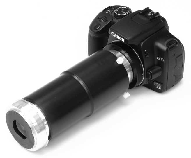
Photo 2. Close-up of TRC-50EX adapter with Canon 400D digital SLR camera.

Photo 3. TRC-50VT console settings for digital photography with the upper-port adapter.
Observe that the "UPPER" indicator is lit, showing that the upper port is selected for photography.
An earlier version of this console uses green push-buttons instead of membrane switches, and the
button is labeled "35mm UPPER".

Photo 4. TRC-50X console settings for digital photography with the upper-port adapter.
Observe that the rotary switch is on "35mm", and the "UPPER" indicator is lit,
showing that the upper port is properly selected for photography.
Further Notes
Adjusting the adapter rotation:
If the edges of the Topcon field are not parallel to the digital image rectangle,
loosen the small setscrews in the EF lens T-mount adapter and
rotate the camera slightly to obtain rotational alignment.
Adjusting the crop ratio:
The crop ratio of the image refers to how the oval Topcon image scales into the digital frame.
The edges of the Topcon image field should normally be scaled to fall just inside the full digital frame;
this crop factor cannot be adjusted except by shimming the relay lens or changing the tube length.
Mirroring in software:
Since the light path to the upper port involves an odd number of mirrors, the image
recorded by the digital camera is mirrored from normal. Since digital images are easily
un-mirrored in post-processing, we have chosen not to build a physical mirror into the
adapter.
Calibrating for parfocality with the adapter focus:
You can adjust the focus of the adapter on the field mask by loosening
the nylon setscrews on the adapter tube and telescoping the relay lens by
trial-and-error in and out of the outer tube. Use the Canon viewfinder
(after carefully calibrating it for your diopter setting) while holding
the adapter up to a diffuse light source to examine the field edges.
The finest focus calibration is obtained by checking the focus of the
field mask with digital images, selecting the highest magnification in the
Topcon instrument (that is, the narrowest retinal field angle). Note that the best focus available
on a 10 megapixel camera image will not resolve down to anything close
to single pixels.
The finest focus adjustments cannot be seen directly in the
viewfinder, and require observing Moire patterns with a 40 lp/mm Ronchi ruling test target such as Edmund Optics part number
38-260, or the variable frequency
versions 38-582 or 43-488 (this last
item being the one we use here in our lab).
Without such a test target, the fine focus point can be laboriously found by making slight adjustments
and viewing zoomed-in test exposures.
If the field mask is in focus in the digital images, but the subject
itself appears out of focus despite your best viewfinder focusing efforts,
then check the parfocality. Parfocality can be difficult to achieve
because it includes every factor in the viewfinder, including: the viewfinder diopter
setting, the calibration of the viewfinder, the observer's refraction Rx,
and the observers (possibly unintentional) accommodation. In general,
each operator will require a specific diopter setting on the viewfinder to
null out the sum of all these focusing factors and establish parfocality
of the camera with the viewfinder image. The best way to determine
this viewfinder diopter setting is to first verify and/or calibrate the
field mask focus as above, and second to take a series of digital photos
of a fixed test subject with a range of viewfinder diopter settings,
yielding a best-focus setting in whole diopters. Given a whole-diopter
setting for best-focus, a second series of photos may refine that setting
to a half-diopter adjustment on the viewfinder eyepiece.
This ultimate best-focus setting may or may not correspond to the eyepiece
crosshairs being viewed in focus, because the calibration of the eyepiece may itself
be off.
Adjusting exposure time (except TRC-50VT models):
The exposure time setting in the Canon camera is chosen to keep the shutter open
during the latency initiated by the camera's signal to the Topcon instrument to fire the flash.
The 1/6, 1/10, or 1/30 SEC recommended above is not necessarily the shortest exposure time possible,
so you may wish to experiment with shortening the exposure time while observing that the
exposure captures the flash illumination. The shortest exposure time is generally preferred,
as this will minimize the light integrated from the steady illumination lamp, improving
the sharpness of the exposure and avoiding any blurring from patient motion.
On the TRC-50VT adapter with asynchronous flash jumper plug and 1/6 SEC exposure time, the
flash lag is already minimal with the upper-port mirror-flip, and shorter exposure times will
miss the flash entirely.
Adjusting adapter speed via relay lens aperture: The relay lens
in the adapter incorporates an adjustable aperture which may be used to
stop down the light path from the instrument. This will decrease the
sensitivity if the digital camera proves too sensitive to the lowest
energy setting of the Topcon flash illumination. Smaller apertures will
also improve the depth of focus on the adapter's relay imaging of the
instrument image (although not the depth of focus on the subject).
To access the aperture adjustment:
- Remove the adapter assembly from the Topcon instrument
and digital camera;
- Separate the outer tube from the relay lens
holder, to expose the relay lens, but first mark the insertion depth
of the relay lens hold into the outer tube, so you can reassemble them
at the same depth later;
- Unscrew the relay lens from the relay lens
holder;
- Observe the aperture setting ring on the relay lens, which
is marked for some range, such as from f3.5 to f22;
- Look through the relay lens to observe
the aperture stopping down as you adjust the setting ring towards the
largest f/number (such as f22);
- Return the relay lens to its holder by screwing it into the holder
tube;
- Make a trial setting of the relay lens aperture by sighting
through the lens while adjusting the setting ring with the relay lens
in the holder (only the tip of the setting ring will now be exposed).
A moderate setting of f8 may yield the sharpest images, if the sensitivity
is sufficient for your desired flash illumination;
- Reassemble the outer tube to the relay lens holder, using the mark
previously made to set the field mask focus, and mount the assembly back onto the
digital camera and the retinal camera;
- Make test exposures and repeat the
adjustments to the aperture until you find an appropriate aperture setting,
considering both sensitivity and depth of focus.
Stopping down the aperture will tend to improve the focus of the adapter on the
Topcon image field, at the expense of brightness.
It will not affect the depth of field or focus of the instrument with
respect to the subject retina.
Adjusting the ISO speed of the digital camera:
The Canon digital cameras offer a range of ISO speeds, from 64 or 100 up to
800 or 1600. This provides you another variable affecting the exposure
of the digital photograph, along with your ability to vary the adapter aperture
(explained above) and the flash energy on the Topcon instrument.
Higher speeds of ISO 200 or 400 will enhance the sensitivity of the camera while
not introducing much noise. Speeds of 800 or more will typically introduce a
degree of speckled noise into the pixels of the photograph, especially considering
that the retinal image is by nature of very low contrast.
Use the histogram feature of the digital camera to analyze your retinal images for
proper exposure level and to observe the degree of contrast.
The position of the hump in the histogram indicates the exposure level, which should
be around the middle of the range, and the width of the hump indicates the contrast
of the retinal image elements.
Cleaning the adapter optics:
Dust on the field lens of the adapter, being close to a focal plane of
the instrument, will tend to show up as a repeating artifact on photos.
For this reason it is important to keep the field lens scrupulously cleaned.
The outside of the field lens can be cleaned in the usual manner with
lint-free non-abrasive tissue (such as Kimwipes) slightly moistened with
glass cleaner, and brushed and puffed lightly with a lens cleaner such
as is sold in photo shops. The Topcon lenses on the rotary turret just
inside the upper port (on some Topcon models), and the Topcon mirrors,
are likewise very sensitive to dust and should be
carefully cleaned. If the inside surface of the adapter's field lens
should need cleaning, unscrew the upper-port fitting from the adapter tube
to access the other side of the lens. For advanced field lens cleaning,
the retaining ring holding the field lens element in the upper-port
fitting may be unscrewed by inserting a small jeweler's screwdriver into
the spanner wrench holes. Remove this element, clean it, and return it
carefully into the upper-port fitting and secure the retaining ring.
Note that the field mask is very thin and exposed metal, and will be
easily damaged if mishandled.
We do not recommend removing dust with a canned-air duster.
These may spit bits of liquid refrigerant which will "frost bite" the lens coating
and cause a permanent spot. If you use a canned duster,
hold the can down on a table top to steady it, and move the item being cleaned in front
of the nozzle, instead of moving the can and possibly swishing the liquid up to the dispenser valve.
Topcon TRC-50EX/IX ONLY: Power the camera down when not in use:
You should manually turn off the power switch to the Canon camera before
powering down the TRC-50EX/IX, because these Topcon models lock the shutter signal
closed when its power is off. This will cause a spurious exposure to be
recorded in the camera, but more significantly it will drain the Canon camera battery
if the camera is left on. If the TRC-50EX/IX is left powered-on but idle,
with the Canon camera also left on, the Canon camera will auto-power-down
to conserve its battery, and reawaken when an exposure command later comes
from the TRC-50EX/IX.
Using an AC adapter on the Canon camera:
To avoid having to worry about having a charged Canon camera battery, you
may wish to purchase the Canon optional item that powers the camera from
an AC adapter.
Lowering resolution on the camera:
Since the highest resolution images of the camera are finer than the optical resolution
of the instrument, you may wish to set the camera to record lower-resolution images.
Tethering software:
If you want to have live previewing and capture of photos on a computer while shooting
with the Canon camera, consider using "tethering" software.
This type of application uses a "tether" from the camera to the computer via a USB cable.
A simple version is included with the Canon camera software support disc.
DSLR Remote Pro (http://www.breezesys.com/DSLRRemotePro/)
is one popular aftermarket package sold for this application.
Contact us for availability of ophthalmological tethering software.
Alternate Canon camera models:
Full-frame Canon digital SLR cameras (such as the model 5D or 5D Mark II) can be used
with the small-format adapters, however the field will be under-cropped
by a 1.6X factor. A slightly longer outer tube must be substituted to
obtain a proper full-field crop. Contact us for availability.
Alternate makes of digital cameras:
Other makes of digital SLR cameras can be used with this adapter, if they provide a similar
format size and shutter/flash synchronization. The adapter incorporates T-mount mechanics
to make interchange inexpensive. Contact us for compabitility information on specific
alternate make and model cameras. Certain Topcon models require a very short shutter lag,
and many less expensive digital SLRs are not compatible because of their relatively long
shutter lag characteristics.
For this reason of critical shutter-lag timing, point-and-shoot cameras are completely unsuitable,
even if they were to be optically adapted.
Limited warranty: We manufacture this adapter to high standards, and guarantee the
performance will be in accord with the specifications. Please contact
me via email (kinch@truetex.com) should you have any difficulties we
can correct.
Copyright 2007, 2008, 2009, 2010 Richard J Kinch.
 .
.