Assembly and Usage Instructions
Richard J Kinch
http://www.truetex.com/
Unpacking: Unpack all items including: main upper unit with magnification changer and slit illuminator, pivot cover, objective lens, joystick base, base axle, base plate with glide surface, (2) rack gears with integral covers, (2) pinion gears, headrest, binocular, (2) eyepieces, beamsplitter, camera adapter, power supply. Leave the shipping restraints on the slit illuminator until directed below to remove them.
Items you must supply: Not supplied: instrument table, screws to attach the power supply to the table. Tools required for assembly: metric hex keys, screwdrivers, drill and drill bit.
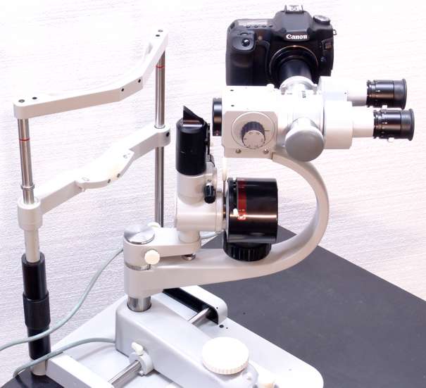
Component identification and orientation: Refer to photos for arrangement of components.
Base plate fasteners: Observe two holes in base plate and supplied mating screws for table top attachment. Note that screws will attach from underneath the table top upwards into the base plate. Screws supplied are for a 3/4" thick table top. If table top is other than 3/4" thick, supply metric screws in a correspondingly different length from those supplied.
Base plate trial fit: Trial-fit base plate location to instrument table top. Patient edge of base plate should be flush with edge of instrument table. Check that prospective location of holes and screws will not interfere with table top supports underneath, and adjust base plate location to avoid any interference. Transfer location of two mounting holes from central area of base plate to instrument table.
Base plate holes: Drill two holes in instrument table to match holes in central area of base plate. Use drill size to clear supplied screws.
Power supply location and mounting: The power supply will mount to the underside of the instrument table, using two screws which engage the keyhole slots on the top of the power supply. Find a location for the power supply which clears any table supports, but is close to the base plate such that the cable and connector from the slit illuminator on the main upper unit will reach around the table edge. Consider the extreme range of travel of the upper unit on the base plate when locating the lamp cable to the power supply. Appropriate screws will vary with the construction of the instrument table top in use, but a typical 3/4" wood table would use a pair of #8 x 3/4 flat head wood screws (not supplied).
Headrest to base plate: Attach headrest to base plate using hex head screws supplied.
Base plate to table top: Attach base plate with headrest to instrument table top using two screws
First rack gear: Attach one rack gear to base plate using two screws and square washers supplied. Use 2mm metric hex key to fasten screws. Insert this key through holes in cover to access screw heads.
Base axle and joystick base: Insert base axle into joystick base through the bearings. Keep the bearing covers on both sides in place.
First pinion gear: Place pinion gear onto one end of axle and insert the base/axle/gear assembly into place on the base plate such that it engages the rack gear.
Second pinion gear and rack gear: Place other pinion gear onto the axle, and engage the gear onto the other rack gear/cover. Engage the second pinion to the second rack in the same position as the first rack and pinion, so that the axle is square to the racks. Align the second rack with the holes on the baseplate and secure with screws and square washers. Verify that the joystick base travels freely on the glide surface.
Upper unit pivot to joystick base pivot shaft: Observe the vertical pivot sleeve on the main upper unit which will engage the pivot shaft on the joystick base. Lift the main upper unit and lower it carefully so that the pivot sleeve couples over the pivot shaft. Screw on the pivot cover.
Illuminator shipping restraints: Remove the shipping restraints holding the slit illuminator to the swing arm.
Illuminator power: Insert power cable from slit illuminator into power supply, routing cable around and underneath patient side of table. Check that cable slack permits full range of motion of both base travel and slit illuminator swing. Connect the AC power cable to the power supply and an AC outlet.
Lamp testing: Turn on the power supply and confirm operation of the slit lamp illumination, including adjustments for lamp intensity on the power supply, circle diameter, slit width, slit tilt, slit sweep, red-free and cobalt filters, and illuminator pivot.
Objective lens: Screw objective lens into the front of the magnification changer. Take care not to touch the surfaces of the lens.
Camera adapter: (If camera adapter is not already assembled to the beamsplitter, perform the assembly as follows:) Remove grey dust cap from one side port of the beamsplitter by unscrewing the knurled lock ring. Assemble camera adapter onto the beamsplitter side port by engaging the adapter to the port face with tabs engaged. Screw beamsplitter port lockring to the adapter and hand-tighten.
Beamsplitter: Assemble the beamsplitter with camera adapter onto the rear of the magnification changer using the dovetail-and-thumbscrew attachment mechanism.
Binocular: Assemble the binocular to the rear of the beamsplitter using the dovetail mechanism.
Eyepieces: Insert the eyepieces into the binocular eyetubes.
Digital camera: Assemble the digital camera to the adapter bayonet.
Remote shutter cable: Connect the joystick button cable to the digital camera remote cable, and the cable to the digital camera.
Eyepiece dioptric adjustment: Proper eyepiece dioptric adjustment is crucial to precise parfocal operation of the instrument with the attached camera. Since the examiner's eyes (including any refraction error) are part of the optical path of the microscope, but not part of the photographic path, any uncompensated refraction error will result in out-of-focus photographs when the microscopic view appears focused to the examiner. Examiners with eyeglasses should remove them when using the instrument and adjust the eyepieces for an equivalent dioptric correction. Adjust the diopter correction setting on each eyepiece to match the corresponding spherical eyeglass Rx for the examiner, if any. For example, a myopic examiner who wears a -2.50D Rx eyeglass lens would set the correction of that eyepiece to -2.5. An emmetropic examiner (perhaps by virtue of contact lenses) would set the eyepieces to zero. If more than one examiner uses the instrument, this adjustment must be applied for each before each examining session. Compensating for refraction error with the instrument focus instead of the eyepiece adjustments will yield out-of-focus photographs.
Test target setup: You may wish to initially test the instrument and its photographic capabilities using a test target. A convenient method for this is to stick a long strip of self-adhesive packing tape between the red canthus marks on the examiner side of the headrest vertical members, with a test target such as a business card stuck on the tape at approximately the eye offset.
Photographic considerations: Generally, manual camera settings (the "M" mode dial setting) instead of automatic or priority modes will be most suitable for instrument photography.
Field of view in camera versus eyepieces: The field of view of the camera via the adapter is about the same height than is seen in the binocular eyepieces, but significantly wider. The camera adapter scales the circular field of view of the eyepieces to fit just inside the vertical aspect of the rectangular camera field. The wider horizontal aspect of the camera field will thus show edges of the microscopic view not seen in the binocular eyepieces. This extra off-axis field visibility is generally not as well focused or optically corrected, since it is intended to be stopped out of the view. To simulate the circular eyepiece field stop, you can apply a circular mask to the rectangular image using an image processing application on a computer.
Diffuse lighting for photographing the entire eye: For low-magnification, diffusely-lit views of the entire anterior eye, the on-camera flash can be directed towards the subject eye with a white card angled in front of the flash lamp. Adjust the flash exposure using the camera's ISO speed setting and aperture, leaving the exposure time at 1/125th second. You may also place external flash units (with or without the on-camera flash disabled) to one or both sides to control the location of the lamp reflex on the cornea. Since the flash unit(s) are so close to the subject, there will be more than enough flash light, and flash intensity settings should be lowered to the extent permitted by the units.
Slit illumination at higher magnifications: For slit illumination, no flash will be available, so you must adjust the camera sensitivity and exposure time to compensate for the greatly reduced light. Use higher settings for ISO speed and exposure time to gain adequate exposure. Higher magnification decreases the effective light intensity, increases the blur from apparent motion, and restricts the depth of field. A very low diffuse flash from an external unit alongside the slit illumination will provide lighting to the anatomical context, instead of starkly slit-illuminated features appearing in a black background. Lighting is as much a critical element of good photomicrography as instrumentation and sensing.
Focus calibration and technique: Photographic technique with the slit lamp differs from classic examination techniques is several ways. Since the camera lacks the ability of the eye to dynamically contextualize and accommodate, photomicrographs are sensitive to focusing errors and depth-of-field limitations. Careful focusing technique is critical to getting sharp pictures, as is parfocal calibration with the eyepiece adjustments. The depth-of-field limitation means that a single photograph cannot focus on all of the three-dimensional structures visible across the field of view, especially at higher magnifications. A photographic series at different focal points can document features which span more than a single focus. Ultimate photographic results are available via focus-stacking software. In short, like photography in general, the camera "sees differently" than the live impression, and this difference is amplified by the instrument magnification, so the photographer must consider the camera's point of view when composing, lighting, and exposing the anatomical scene.
Disassembly for shipment: In the event you should need to ship the instrument, here is a list of the disassembly items to reverse the assembly into smaller components suitable for shipping: