
November 2002.
One of the great things about metalworking as a hobby is that you are equipped to make much of your own tooling, either for economy, for entertainment, or to fill-in some last-minute component you might need to finish another project. If you're still learning the techniques, then such items make good practice objects, since the finished results just have to work, they don't have to look pretty. You must nevertheless take care that you don't spend hours and hours making some tool that costs a few dollars, which is increasingly likely with the way imported tools continue to improve in quality and decrease in cost.
In this project, I found myself needing a boring bar but having no quick source for a ready-made tool. I did have on hand the materials and the tooling to create one, however.
Standard boring bars have a round shank with a typical diameter of 3/8 or 1/2 inch. Mounting the round tool on the lathe toolpost requires a separate adapter. In making my custom boring bar, I decided to mill a square shank that would directly fit the minilathe toolpost without needing an adapter.
The minilathe toolpost provides a gap of 5/8 inch, with 5/16 inch above and below the center axis of the lathe. So I made the square shank of the boring bar slightly under 5/8 inch thick, with a length of 2 inches to match the toolpost. The shaft portion could be any diameter and length, but I chose a matching 5/8 inch diameter since this is about the largest size which can still reach into a 7/8 inch pilot hole, which in turn is my largest drill bit. The large diameter would also be more rigid and make for easier machining for the bit attachment. I chose a shaft length of 2 inches (overall length 4 inches), which is a good fit to the limits of the minilathe and my typical applications.
I started with rough stock consisting of a length of 7/8 inch round structural steel bar. For a 4-inch finished piece, I started with a 6-inch length, which left an extra inch on each end for clearance from the chuck and tailstock. I mounted this length of rough stock in the 3-jaw chuck, with the other end free, and spun it slowly, stopping and adjusting the tilt in the chuck to roughly minimize runout. Then I used a stubby drill in the tailstock to drill a dimple for the live center, and fixed the tail of the work in the tailstock with the live center. I removed the rough mill finish from the 2-inch portion that would become the square shank, leaving a trued cylinder with the largest diameter possible inside of the old finish. On the adjacent 2-inch portion that would become the shaft, I turned down the diameter to the finished dimension of 5/8 inch. I used a parting tool on both ends and finished the parting with a hack saw.
On the vertical mill-drill, I clamped the shaft with a V-block in the milling vise on the table, and face-milled even amounts off the 7/8-inch round shank, leaving parallel faces slightly less than 5/8 apart, which are the mating faces for the toolpost. Although not strictly necessary, I rotated the shank 90 degrees and milled 2 more parallel faces on the shank. The angle of this rotation is not critical, since these faces do not meet anything; indeed these two faces could yield a trapezoidal cross-section to the shank.
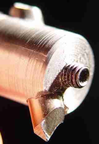
Below is a close-up of the bit attachment. The usual design is for the bit to be at 45 or at 90 degrees; I chose 45 degrees since the cut can reach all the way flush to the chuck at that angle. By using 1/4 inch drill rod for the tool bit, instead of a the usual square tool bit, I avoided having to broach a square keyway in the shaft and could instead simply drill a 1/4 inch hole. The disadvantage is that one must take care to keep the round bit rotated in the right alignment, rather than having a square hole to force alignment. The corner of the shaft tip must first be milled flat, also at a 45 degree angle, to accept the drilling of the hole. The holes for the bit and setscrew, as well as the milled starting face, can be made on the lathe, using drill bits and an end mill held in the chuck, with the bar mounted in the normal way on the toolpost.
The piece of drill rod for the bit must be cut long enough to fill the shaft, to project a tooth, and to provide extra length for repeated sharpening, but not so long as to have a tail that interferes with the opposite side of the bore. Drill rod is easily cut by notching with the grinder wheel corner and snapping the notched point in a vise.
I drilled and tapped the end for a #10-32 setscrew. In retrospect I should have moved the bit placement further away from the end of the shaft. This would provide more engaged threads on the setscrew. To bore flush if need be, the tip of the setscrew will have to be ground down to keep it from standing out of the bar as shown. Or, the position of the setscrew could have been move off-axis.
The bit tooth is ground from three faces. First, the end is ground down to be perpendicular to the axis of the shaft. Then the outside of the bit (facing toward you and up in the photo) is ground to relieve the bit from the trailing face of the work. Finally, the top of the bit is ground to provide a hook to the remaining projection.
February, 2004.
This tool is also useful with a tiny threading insert for cutting inside threads on the lathe. For the insert, I took a bit more of the 1/4" round tool material, and ground it to make a 60-degree-triangle thread-cutting point that (including the 45-degree holding angle) aligns perpendicular to the turning axis of the work. With this, I was able to cut the so-called "C-mount" inside threads (that is, 1"-32) for optical devices.