Updated: May, 2019.
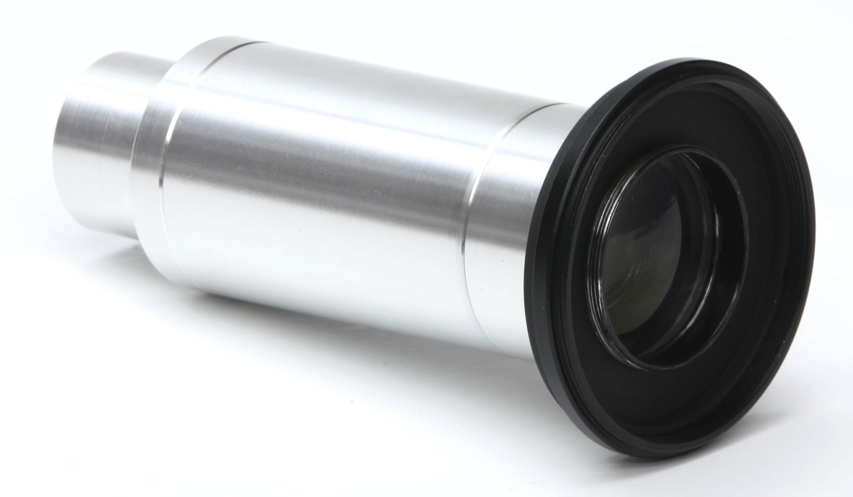
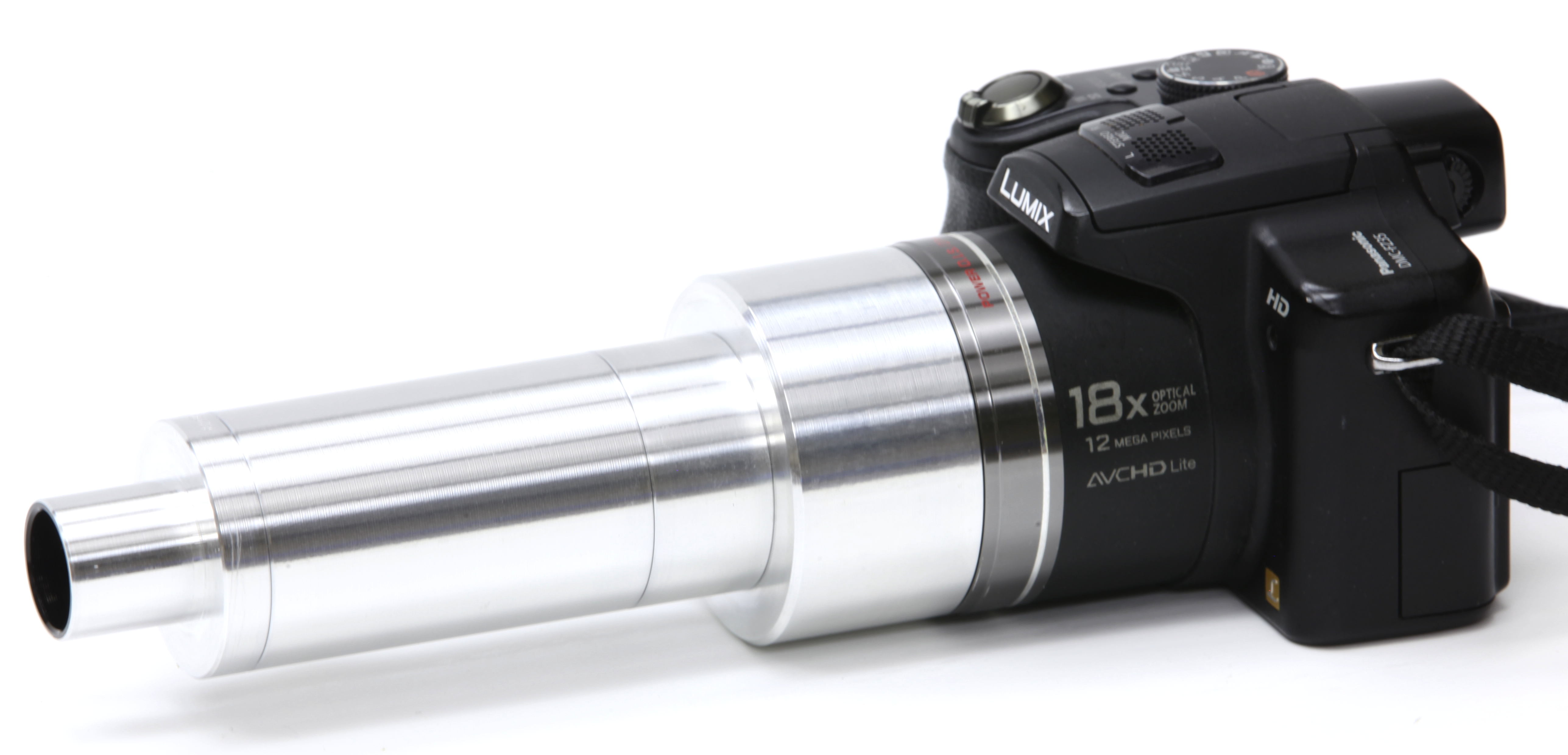
This document describes how to install and operate the adapter for large-lens cameras to microscope eyetubes. This adapter is designed to attach cameras and camcorders with large, zoom lenses to standard microscopes for high-quality still or video photography. The adapter provides high-resolution, low-distortion, zoom-adjustable, widely-compatible imaging performance.
The adapter consists of a threaded stack of individual modules. This is supplied as an assembled unit ready to couple a specific camera to a specific microscope, as specified in your original order. You may selectively assemble and reconfigure the module options supplied in the full kit to fit a wide variety of camera lens sizes and microscope eyetubes.
Part numbers (abbreviated "P/N") below indicate the parts of the assembly we manufacture. Minor parts such as filter-thread fittings do not carry a part number, because these are industry-standard items readily available from many suppliers.
The term "eyetube" means the receptacle on the microscope which normally holds an eyepiece. The camera adapter provides an eyepiece-sized end fitting, which inserts into the microscope eyetube.
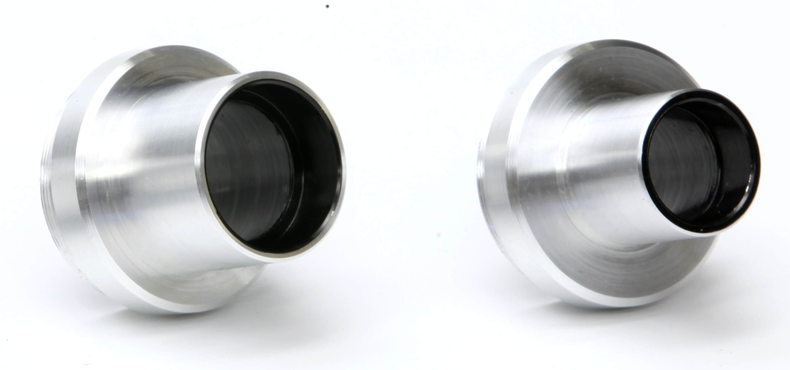
Identify the kit contents and modular logic:
These eyepiece fittings are all mutually parfocal, to ensure compatibility with the various focal plane locations established by the varying microscope optics.
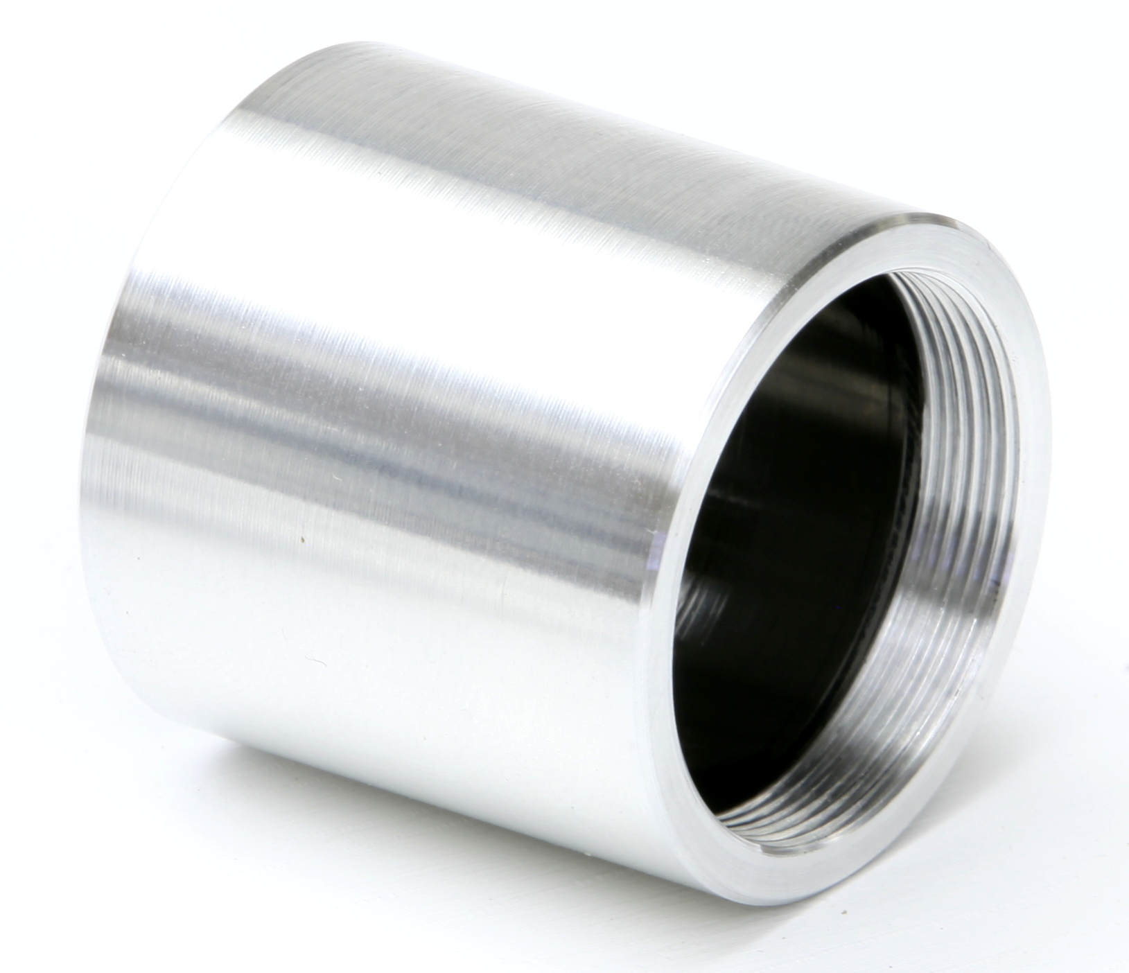
The eyepiece fitting may be switched among these available types, by unscrewing the fitting from the end of the main tube assembly, and then screwing in another size fitting.
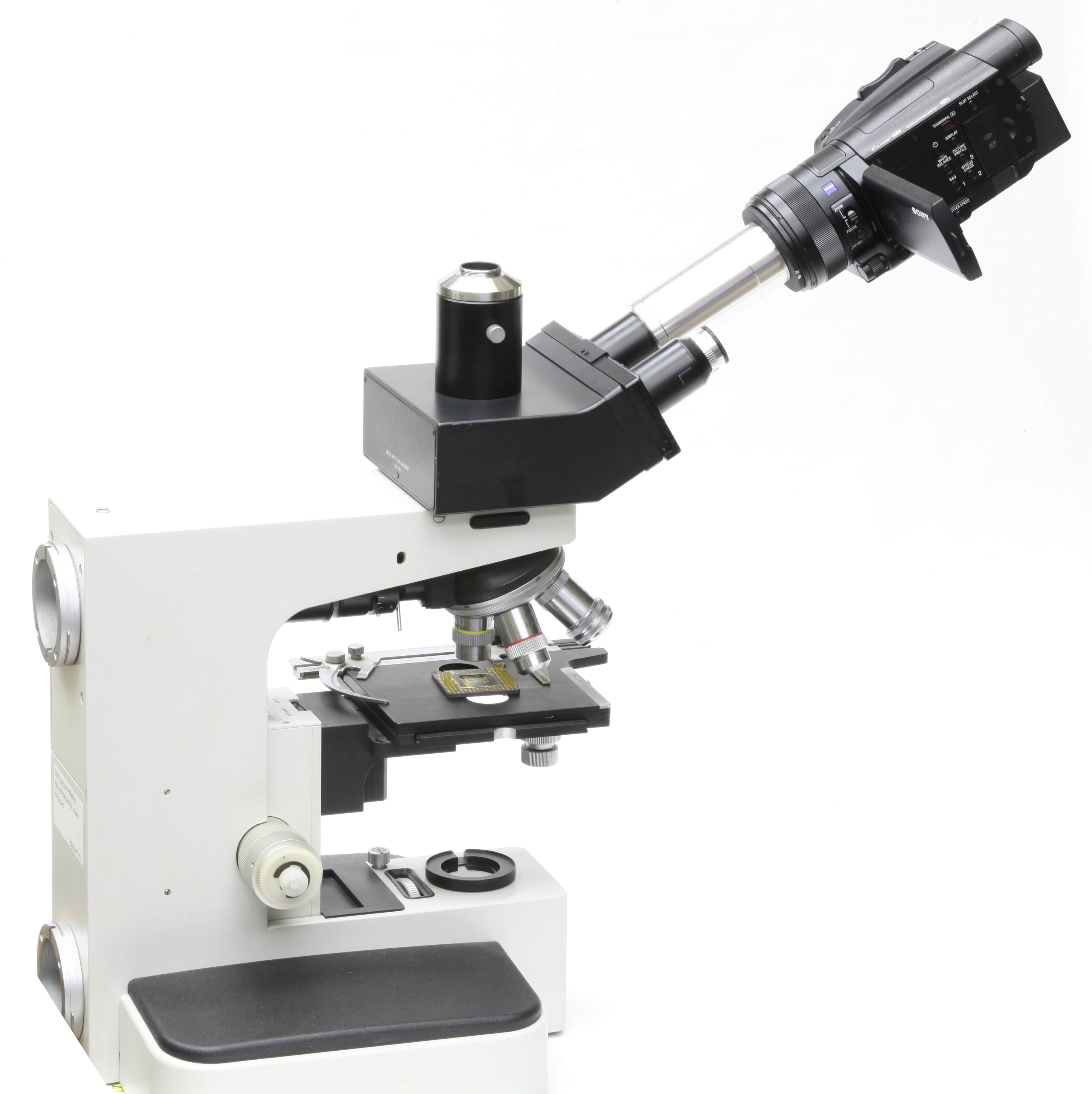
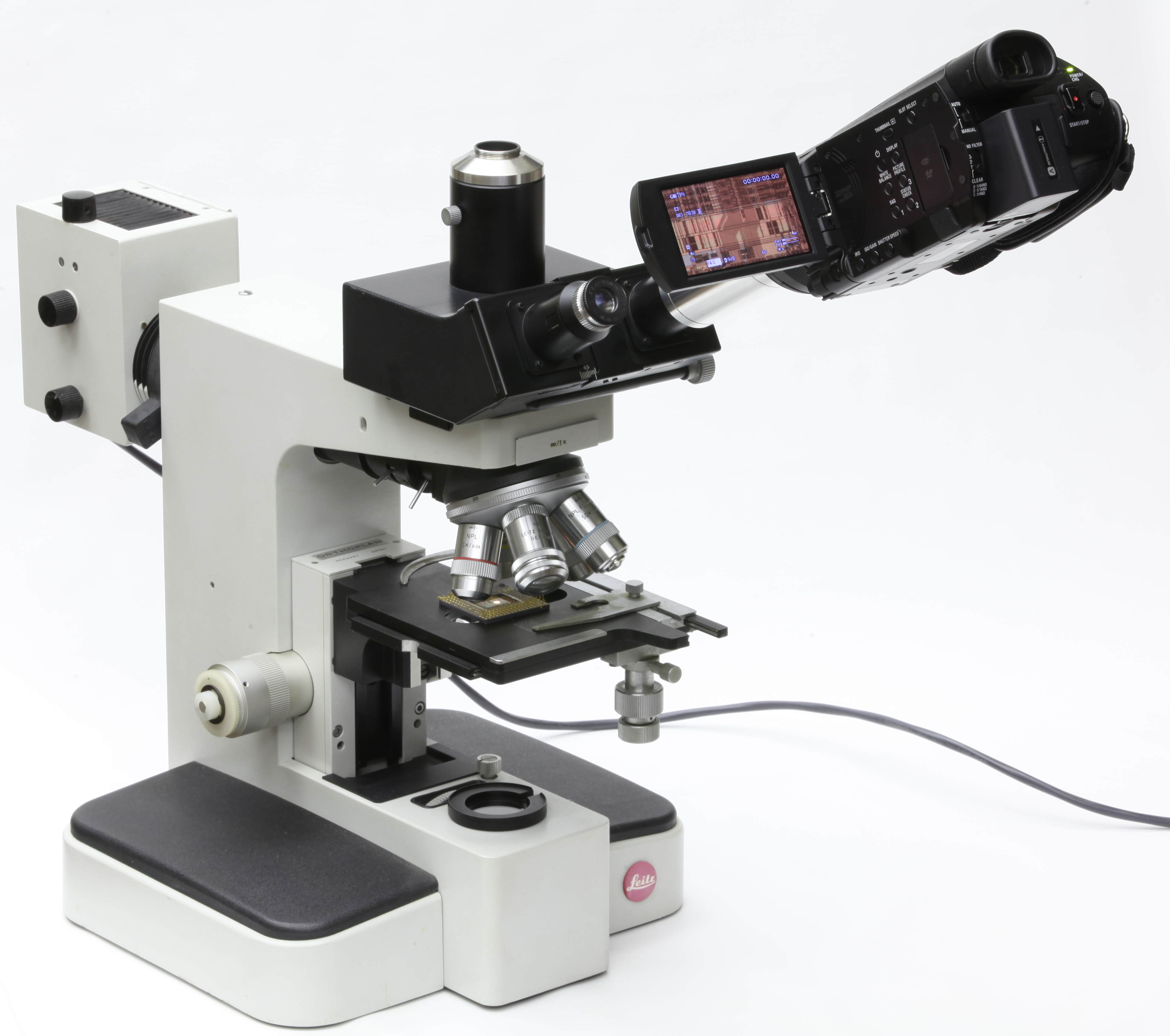
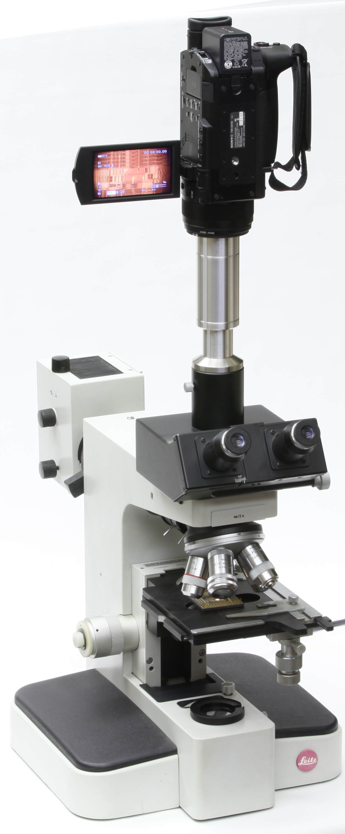
Installing the adapted camera on the microscope
Caution: Camera filter threads are very fine and delicate. Inserting removing threaded couplings requires careful handling to avoid damage to threads. Use care to start and engage the threads properly between the mating components. Proper engagement will not exhibit binding or require excessive force. If you sense cross-threading, binding, or other difficulty, then gently back the component out, and try again. This applies to both ends of the adapter: the attachment to the camera lens and the installation of the eyepiece fitting(s).
Deciding whether external mechanical support is needed
Depending on the weight of the camera, and the orientation of the microscope eyetube, the camera may require mechanical support to rest feasibly in the microscope.
Setting the camera cropping and achieving sharp focus
Set the camera's optical settings as follows:
To begin photography, set up a microscopic scene which you have focused visually in the eyepiece. Follow proper laboratory techniques of visual focusing: relaxed accommodation, corrected distance vision (contact lenses, glasses, or if available, diopter settings on the eyepiece). Once you have the camera working, further observations may proceed with the camera alone, if you wish to avoid visual eyepiece procedures.
With the camera at widest-angle zoom, the view will show only a small circle of light in the center of the field of view. Zoom in to achieve the image cropping suitable for your observation. This adjustment will allow you to fill the camera field of view with the scene, or vary the zoom magnification between a wide-field cropping versus enlarging the central portion of the scene.
Once you have established a suitable field of view and cropping with the zoom adjustment, you will likely need a small adjustment to bring the camera image to sharp focus. Use the microscope focusing to achieve camera focus. Do not adjust the camera's manual focus; leave the camera manually set to infinity focus, and use the microscope to focus.
Calibrating parfocality
If the visual view in the eyepiece is not in sharp focus (that is, not parfocal) when the camera is in sharp focus, you may either work within that circumstantial limitation (adjusting focus for one or the other, as needed), or you may calibrate the microscope for parfocality with the camera. Ideally, the two imaging systems (human eye and the eyepiece, versus camera and adapter) would be precisely parfocal, but this is not usually the case "out of the box". Parfocal calibration may available by various means: adjusting a diopter setting on the eyepiece if available, choosing an eyewear correction to establish distance vision (the eye being part of the optical system which must match the camera's infinity focus), or by moving the eyepiece out slightly from its eyetube and fixing this position with a collar.
It may be possible to calibrate parfocality by adjusting the camera's manual focus, but this is typically not convenient. Digital camera focus adjustments are usually lost when the camera is powered down, and must be repeated when turning the camera on. From the camera's point of view, the adjustment required for parfocality may be in the direction of "beyond infinity", instead of closer distance, and most camera lenses do not provide "beyond infinity" focus.
Due to variations in eyepiece standards (the eyetube diameters are standardized, but the location of the focal plane within the eyetube is not standard and varies slightly among manufacturers), it is normal that parfocality is not precisely calibrated without performing some adjustment. The adapter is designed for an average focal plane location, but a given eyepiece is not necessarily average in this regard, as there is no controlling standard. Hence some adjustments to the apparatus will likely be necessary to achieve parfocality.
Understanding cropping and camera optics
The cropping choices available with a zoom lens will ideally range from an inscribed, outscribed, or magnified central portion of the microscope's circular full field of view. See the document explaining cropping principles (http://www.truetex.com/cropping.pdf) to understand how a rectangular camera field of view necessitates a compromise choice when imaging a microscope's circular field of view.
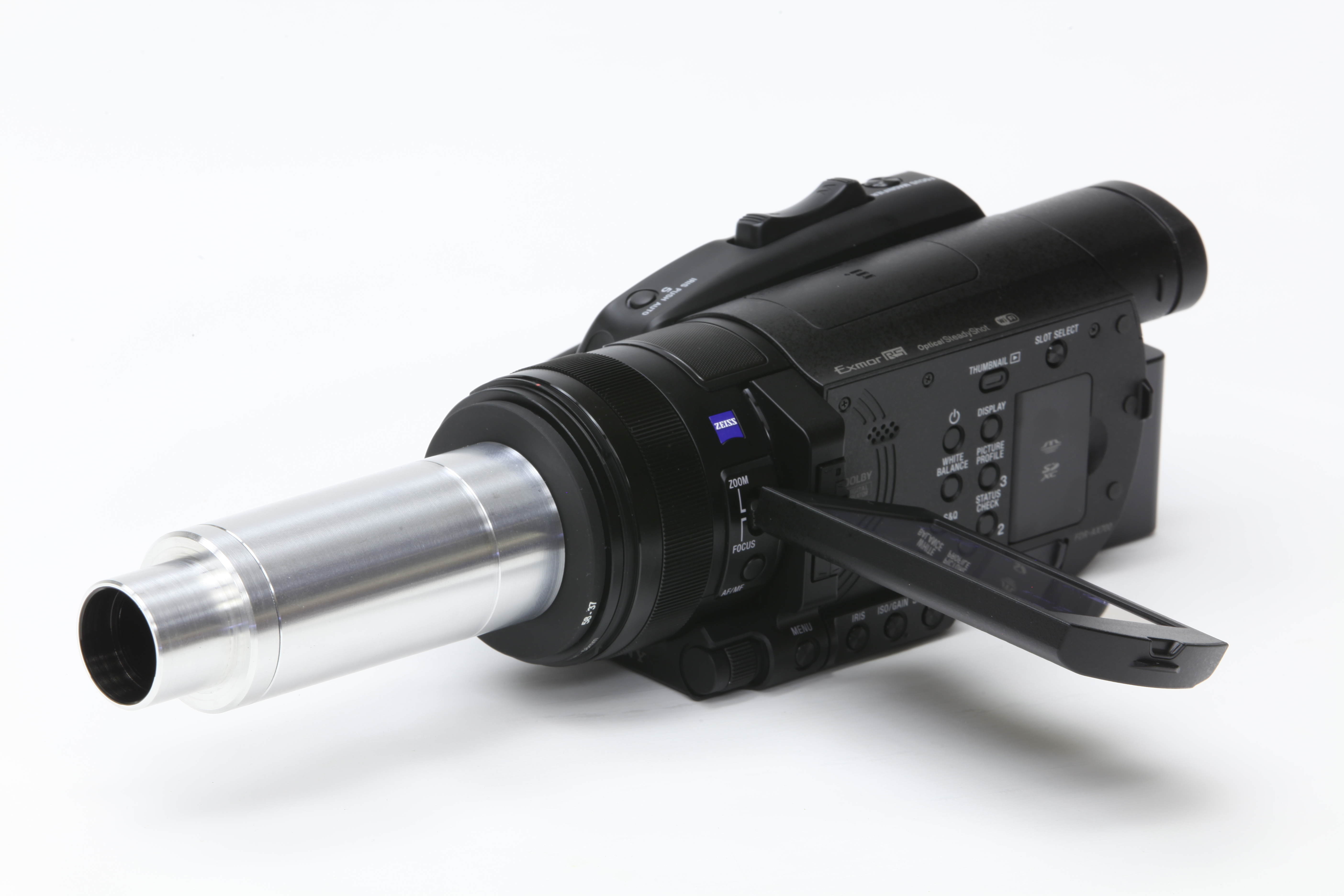
The range of cropping modes available with a given camera depends primarily on the zoom range of the camera's built-in optics, and secondarily on the speed (f/ratio) of the lens across the zoom range. High-end camcorders typically provide a 10X optical zoom range and f/2.8-f/4.0, which provides a versatile range of cropping. More modest camcorders typically provide a 4X optical zoom range, and in some cases low speed (high f/number) over the telephoto range, either of which may which may limit the available cropping to the inscribed to outscribed range, with a highly magnified central view not possible or vignetted.
For DSLR or mirrorless (Four Thirds) cameras, a low-cost kit lens such as the 18-55mm, or high-end 24-105mm, are suited to this adapter. Zoom lenses beyond the 50mm to 100mm range are not suitable, as these focal lengths will not provide a useful cropping. Prime lenses in that range are suitable, but provide only one fixed cropping choice. The appropriate prime lens for an between-inscribed-outscribed compromise crop would be 60mm for an APS-C or DX format sensor, or 100mm for a full-frame format sensor, with f/4, f/2.8, or larger aperture. The entrance pupil (the appearance of the aperture stop or iris when viewed through the front of the lens) should be no closer than 25mm from the front surface of the lens, which is usually the case.
At the extreme ends of wide-angle or telephoto settings of the camera's zoom, you may encounter vignetting of the image. That is, the edges of the image may become dim, lower contrast, or altogether dark. Vignetting may intrude on either end of the zoom range, or both, or neither, depending on the optical design of the camera. Vignetting will also occur if the manual iris setting is inadvertently set to a smaller aperture (higher f/number), or if the camera lens speed does not provide a fast lens (f/2.8 to f/4.0 over wide-angle to telephoto zoom). The adapter optical design is best capable with zoom lenses having entrance pupils about 25mm (1 inch) deep inside the front filter receptacle at the extreme wide-angle zoom setting, which is a typical characteristic of larger handheld camcorders, and compact zoom lenses for DSLR cameras. Smaller format lenses with a closer entrance pupil require a different, smaller adapter to avoid vignetting.
Reconfiguring the adapter for other cameras, using stock step-down rings
You may readily reconfigure the adapter to work with any camera providing a standard lens filter thread. The adapter as supplied is normally configured for the camera filter thread size specified at the time of order. The fittings to the camera lens are stock step-down rings readily available from camera parts suppliers. Thus you may reconfigure the adapter to work with a different lens that provides a different filter thread than originally supplied on the adapter.
Filter threads on camera lenses typically provide one of a standard series of sizes specified in millimeter diameter. These sizes are to following steps: 25mm, 27mm, 28mm, 30mm, 34mm, 37mm, 43mm, 46mm, 49mm, 52mm, 55mm, 58mm, 62mm, 67mm, 72mm, 77mm, 82mm, 86mm, 95mm. The adapter tube itself provides a 37mm filter thread. Thus to fit the basic adapter to a given camera filter thread larger than 37mm, you would use a stock step-down ring from the camera's specific filter thread to 37mm. For example, a camera lens with a 52mm filter thread would require a 52-37 step-down ring, a 58mm lens thread would require 58-37 step-down ring, etc.
The term "step-down" ring indicates that the ring provides a larger diameter outside thread (male thread), and a smaller inside thread (female thread). This makes step-down ring(s) the appropriate fitting to attach the microscope adapter (which provides a 37mm outside thread on the camera end) to the filter thread of a given camera lens (which provides a larger inside thread, such 52mm, 58mm, etc.).
Step-down rings are most commonly available in one or two incremental steps in the series, making it necessary to stack two or more rings to span a larger difference. For example, to fit a 62mm camera lens thread to the 37mm adapter tube might require stacking a 62-58 step-down ring on a 58-37 step-down ring, because those steps are readily available, while a single 62-37 step-down ring is not available.
To remove the step-down rings from the original adapter, as supplied, be aware that the threads will have a small portion of weak thread-locking compound applied. The step-down ring(s) will require a firm twist to loosen from the adapter; this is intentional to prevent the step-down assembly from loosening during its normal use. Likewise, you may wish to apply a similar thread-locker when assembling a different configuration of step-down ring(s). The appropriate compound to use is simply a dab of black paint, nail polish, nitrocelluose adhesive (household cement), or rubber cement. Brush any of these onto a portion of the threads. They will hold the threaded assembly together firmly, but are readily disassembled on occasions when that is required.
To assist disassembly of thread-locked joints that resist hand torque, you may apply a moderate heat from a heat-gun or laboratory oven, but no more than 125 deg C (257 deg F). This is hotter than you can grip comfortably with bare hands, so a practical rule is to apply heat until the assembly is barely tolerable to hand-holding. This temperature is enough to soften the thread-locker, but well below the damage threshold for the optical cement used in the lenses.
Step-up rings are thin, making stacks of them difficult to grasp and separate from each other without special tools. If your configuration-switching requires more than one stack, it is more convenient to acquire duplicates of the inexpensive step-down rings, treating each stack as permanent as a unit (but exchangeable for other stacks). This duplication is not costly, and avoids having to separate individual rings. With thread-locker, individual rings are nearly impossible to separate from each other, but stacks of them will typically separate from the tube with hand torque, since the tube acts as a handle to provide a grip.
Do not use industrial thread-locker on any part of the adapter assembly, such as Loctite, and do not improvise with Super Glue. These are cyanoacrylate adhesives which are too strong and too permanent for this application. Cyanoacrylate products also emit fumes when curing, which are capable of damaging coatings on lenses and tube blackening paint.
The black paint on the internal surfaces is necessary to prevent stray light from degrading image contrast. If the paint is damaged to a significant degree, exposing the bright metal on the inside of a tube, you may touch it up with flat black acrylic paint or a dry-erase marker. Black permanent-marker pens leave a thin coat and are not as effective as flat black paint, but better than bare metal if paint is not available.
When selecting and acquiring step-down rings to use with the adapter, do not confuse them with step-up rings. Step-up rings consist of the inverse inside-outside logic compared to step-down rings. That is, a step-up ring provides a smaller outside thread and larger inside thread, the reverse of a step-down ring which provides a smaller inside thread and larger outside thread. Step-down rings are required for the camera-microscope adapter, so take care to acquire step-down rings in the matching sizes, when you aim to reconfigure the adapter for a different camera lens thread.
Copyright 2018, 2019 Richard J Kinch.