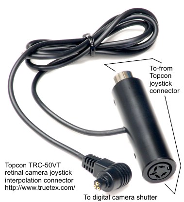
Photo 1. Joystick interpolation cable with Canon N3 remote connector.
Canon E3 remote connector (2.5mm submini plug) for Canon Rebel model SLR cameras may alternatively be provided.
An E3-N3 adapter, and E3-Nikon adapter are also available.
Richard J Kinch
http://www.truetex.com
April, 2012
Topcon model variations: Topcon produced several variations of the same basic instrument design, depending on the presence of a tilting mechanism (the "T" in the model designation) and/or the upper accessory port. The TRC-50VT was the most common model and also the most capable, providing the tilting mechanism and both upper and rear camera ports. The TRC-50V was relatively rare and did not provide the tilting mechanism. The TRC-50F provided a rear-port camera attachment only and no tilt, while the TRC-50FT added the tilt mechanism. The "F" models provided a switchable field of view of either 20 or 50 degrees, while the "V" models provided 20, 35, and 50 degrees. All were equipped to photograph in color or fluorescein angiography. Support electronics and flash power were provided in separate floor-mounted power supply cabinets. The controls for the "V" models were housed in a separate keyboard console mounted on the instrument table, and were more complex having to provide various settings for upper-port accessories. The "F" model controls were simpler and built into the top of the power supply cabinet.
The optics, electronics, and mechanics of these instruments were of the highest quality, both in design and execution. These instruments should continue to serve for many decades into the future when upgraded with the versatility and economy of digital photography.
Kit contents: This portion of the digital adapter kit consists of:
Step 1: Identify the ends of the interpolation cable and the cord to the camera remote connection. See Photo 1 above.
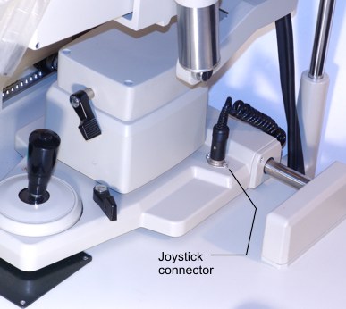
Step 2: Locate the existing Topcon joystick connector plug and socket on the Topcon instrument. See Photo 2 above.
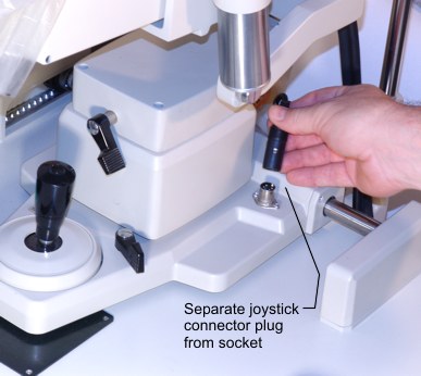
Step 3: Separate the Topcon joystick connector plug and socket by pulling up on the connector body. See Photo 3 above.
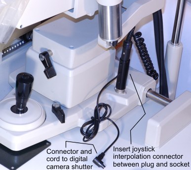
Step 4: Insert the ends of the new interpolation connector into mating ends of the Topcon connector plug and socket. See Photo 4 above. The new connector end with the silver metal collar inserts into the loose end of the old coiled cord. The other new end inserts into the existing metal connector mounted on the Topcon joystick base. The connectors must be rotated for proper alignment to fit together. That is, the interpolation connector must be rotated so that the holes and camera cord are facing the rear of the instrument (that is, towards the operator). Observe the notch and tab in the connectors to establish this alignment. The fit should be snug to the connector in the base of the Topcon unit. Press the new connector firmly down onto the base of the Topcon unit, making sure that the connector is fully seated.
Route the digital camera cord up the side of the instrument to the upper rear where it will connect to the digital camera. Use cable ties to fasten the cord to the instrument. Allow enough cord slack for full pan, tilt, and travel of the upper unit.
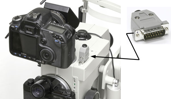
Step 5 (for upper-port adapters ONLY, not rear port): Insert the asynchronous flash jumper plug onto the DB-15 connector. See Photo 5 above. The jumper plug consists of a DB-15 connector with a stub cable. This jumper plug does not connect to anything else; the cable portion ends in a stub. The jumper plug causes the Topcon flash to fire as soon as the mirror has flipped for the upper port; the digital camera will already have its shutter open since it is faster than the mirror flip. Important: Set the digital camera manual exposure time ("M" mode dial setting) to: 1/6 second. If pictures sometimes miss the Topcon flash, increase the exposure time to 1/5 or 1/4 second, until the flash is reliably captured. Do not use the 1/20 SEC setting we suggest for synchronous flash connections on other Topcon models. Setting a faster shutter speed will cause the digital camera to miss the flash illumination and result in dark digital photos. Note that if the camera is "asleep" from the Canon auto-power-off feature (where the camera turns itself off if no action occurs), that the interpolation shutter control will "wake" the camera, but the first photo will be dark, since the camera responds with a very long shutter lag when in the "sleep" state.
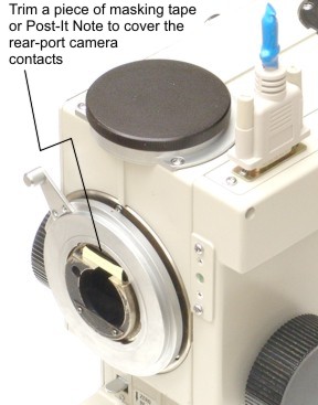
Step 6 (for upper-port adapters ONLY, not rear port): Trim a piece of masking tape or the sticky part of 3M Post-It Note to approximately 5mm high by 27mm wide. Remove the Topcon film camera body from the rear port. Apply this paper to cover the gold camera contacts on the rear port, as shown in Photo 6 above. Return the film camera body to the rear port. You will use the original, superb Topcon viewfinder to frame the digital photos taken by the upper-port adapter and digital camera. (Should you ever want to revert to film photography using the rear port, you can easily remove this paper cover.)
Additional steps: Proceed with installation and testing of the digital camera adapter on the upper port or rear port of the Topcon instrument.
Additional notes: