One of my projects is conversion of the mill-drill to CNC control. This involves replacing the axis handwheels for the table (X and Y axes) and for the quill (Z axis) with computer-controlled motors. I improvised my design after reading Dan Mauch's 1998 post in rec.crafts.metalworking, "Converting a Mill-Drill to CNC" (see the thread on Google here).
This story begins with the Y-axis conversion after I had finished a first version of the X-axis conversion. I converted the X-axis first because it is quite useful as a lone CNC axis, applied like a glorified power feed. Motors and other components for CNC are expensive, so I didn't want to commit any more than necessary on designs which might have to evolve. I say "first version" of the X-axis, because it was essentially Mauch's simple design, which I crudely implemented, machining the steel bracket using a completely manual mill. I hope to replace the X-axis bracket with some improvements, of which the Y-axis described below begins to suggest, with the X- and Y-axes "bootstrapping" themselves to create improved designs.
I scrounged motors, encoders, timing pulleys, and timing belts on eBay one odd piece at a time, which is so cheap that my shop has filled to be a veritable R&D laboratory for various stepper and servo designs. I studied electric motors, control theory, and circuit design as part of my engineering education, but after many years in computer hardware and software, this is the first project for me that applied many of those more mechanical-motion topics. Innovations like the Web, Google, and eBay makes things much easier on a small scale than they ever were not too many years ago. Technical knowledge, collegial interaction, and exotic parts and tools, once the provence of large university and industrial labs, are all available by simply clicking buttons. The notion of having a "Santa Claus machine" (takes raw materials and machines them to whatever you imagine) holds enough promise that I was compelled to build it.
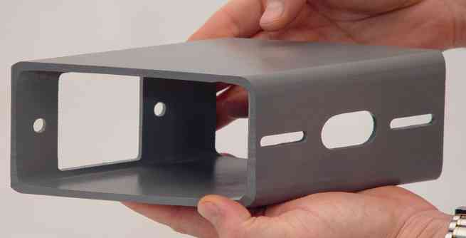
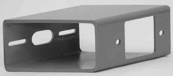
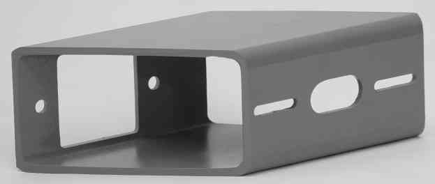
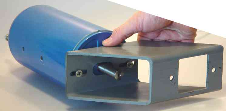
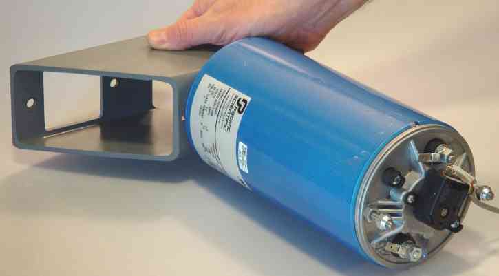
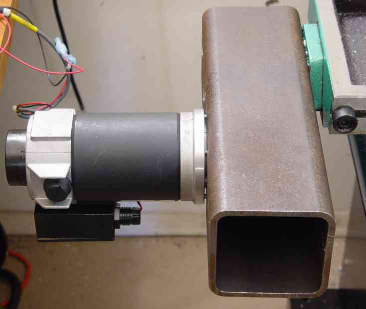
The Y-axis mounting bracket turned out much better in fit and finish than the X-axis, after the experience with the form and function of the X bracket, and having the use of the X-axis CNC control for single-axis moves. A 45-degree, diagonally-cut design (see more photos below for better perspective) provides convenient wide-open exposure of the mounting bolts, timing pulleys, and timing belt, while maintaining a rigid mounting. The motor adds hefty 20 lbs to the assembly, and this weight is applied with a considerable leverage to pull against the face of the handwheel mount.
Snap-on covers will (someday) protect the exposed areas in use, to prevent contamination with chips or coolant, and to prevent hazards from moving parts (for the moment, keep your waist-high anatomy clear!).
Why use a belt and pulley arrangement to couple the motor to the leadscrew shafts? At least two important reasons: (1) The pulley-and-belt mechanism solves the shaft alignment problem, a critical issue for any motor-driven axle. No rigid coupling of the shafts with a rigid motor mount would ever perfectly align, and the result would be a destructive binding of the bearings in the mechanism, so there must be some allowance for shaft misalignment. While components like helical couplers can solve the alignment problem, a pulley arrangment is efficient, inexpensive, and allows an additional freedom to choose a desirable pulley ratio. (2) The servomotor typically has too much speed and not enough torque for the application, so you want to trade speed for torque using a pulley ratio (although I have used a 1:1 ratio in this example). The servomotor maximum torque translates into a maximum linear force on the machine table, and this maximum available linear force limits the maximum controlled cutting speed that the system can achieve, since the faster and deeper the cutting, the larger the reaction force which must be overcome. On a very lightweight machine tool of this type, typical feed rates for cutting passes are further limited to a maximum of perhaps 10 inches per minute (ipm), which is a typical maximum cutting rate which the rigidity of the machine can support. Since each turn of the leadscrews translates to 0.1 inch of travel, the leadscrews should thus turn at about 100 rpm. We might configure the maximum controllable shaft speed of a 1800 rpm servomotor at perhaps 1000 rpm, to leave some rpm "headroom" to maintain the servo lock. This would suggest about a 10:1 reduction ratio in the pulleys to achieve 100 rpm at the leadscrews and thus 10 ipm on the table. But since we want to also move the machine table quickly ("slew" it) when not cutting (100 ipm slewing would be a goal on a small machine such as this, while industrial machining centers slew at 500 or more ipm), a compromise is in order to perhaps a 2:1 or 4:1 ratio. The compromise available is further limited by the room available inside the 4x4 stock used for the motor mounting.
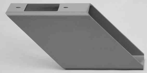
I started with raw stock, a 6-foot length of 3" x 4" x 0.180" rectangular channel structural steel, obtained as a rusty drop from the local steel supplier. From this I cut off a symmetric diamond shape with the metal-cutting bandsaw, holding the work in the saw vise at 45 degrees to the blade. The 4-inch side of the stock lays flat in the saw vise, and the saw cuts through the 3-inch depth. I designed a nominal length of 5.5 inches for the 3-inch high faces based on the motor sizes and separation required for the timing pulleys and timing belt I would be using. The 5.5 inch face, together with the span of 4 inches from the diagonal cut, less some trimming to remove the sharp ends, yields an overall length on the diamond (if stood vertically on the end) of about 9 inches. I sandblasted this rough piece to remove the surface rust, revealing a smooth and stable reddish-black oxide finish.
Machining this part consists of preparing the two faces which will mate to (1) the mill handwheel bearing plate and (2) the servomotor face, respectively.
Before the functional machining, I ran a side-mill along the various razor-sharp wedge edges of the diamond-shape component. The part would not be safe to handle without these edges removed.
To machine the handwheel-mating face, I first face-milled about 0.020 from the rough side to give a flat surface, since the faces of the structural steel are forged with a slight outward curvature. Rigid clamping of the bracket faces to the mating components requires the faces to be precisely flat. I then used a 1/4" mill on a 2" square path to cut a hole for the handwheel projection. This hole allows the widest part of the handwheel shaft (namely the knurled ring next to the inch scale) to pass through. Symmetrically on either side of this hole are 8mm ("O" drill) holes spaced on 80mm (3.149") centers, with a setback of 0.75" from the center of the hole closer to the edge. Through the holes pass metric bolts that replace the stock screws that fasten the handwheel bearing plate to the base of the mill. All these holes are sized and separated based on measurements I took from the mill.
To machine the servomotor face of the bracket, I milled an oblong hole with a 0.75" mill moved along the axis by 0.375" from the center in both directions. This yielded a 0.75" wide and 1.50" long oval slot for the servomotor shaft. For the motor mount screw slots, I milled with a 0.25" mill over a length of +/- 0.5" from the center, yielding an oblong slot 0.25" wide by 1.25". The centers of these oblong slots are separated by 3.5 inches, which is dictated by the faceplate of the motor I am mounting. These oblong slots allow various motor sizes and mounting types to be adjusted for belt tension. I finally face-milled the mounting face for a flat mating surface. The inside of the structural steel has a seam ridge inside, which must be painstakingly ground down with a die grinder.
I finished the part with (1) Loctite Extend rust neutralizer-primer spray and (2) Rust-Oleum industrial spray enamel V2187 ("dark machine grey"). These yield a tough and corrosion-resistant finish to the steel. The Extend product alone creates a pleasant black finish on sandblasted steel, and a purplish-black finish on clean bare steel, that develops over a day or two, and which is suitable for a final finish if you like the colors.
It would be an improvement to have an extra 0.5" or 1.0" in length, and the corresponding extensions to the oblong holes on the servomotor face, which would increase the adjustment range of the pulley separation.
| Rough stock outside dimensions | 4" x 3" x 0.180" structural steel |
| Rough stock inside dimensions | 3.6" x 2.6" |
| Overall length (OAL) of cut piece from stock | 9.5" (*) |
| Incremental length of stock consumed per piece cut | 6.0" (*) |
| Weight of finished bracket | 3.2 lbs (1.37 kg) |
| Hole for handwheel passage | 0.25" mill on 2" square path |
| Holes for handwheel mounting bolts | 8mm = 0.315" (letter "O" drill) |
| Hole for motor shaft | 0.75" mill on +/- 0.375" path along length, OAL 1.5" |
| Holes for motor mounting bolts | 0.25" mill on +/- 0.5" path along length, OAL 1.25" |
| Bolts (handwheel face mounting) | M8-1.25 x 20 metric (removed from original factory assembly) M8-1.25 x 40 metric (longer replacements for attaching bracket) |
| Timing belt series | "L" section (0.375" tooth pitch) |
| Pulley types | 16L050 timing pulleys, e.g., MSC P/N 35376110 (1/2" bore) MSC P/N 35376128 (5/8" bore) MSC P/N 35376136 (3/4" bore) |
| Pulley flange OD | 2.125" |
| Pulley flange clearance to inside of bracket | 0.25" |
| Belt type | 150L050 timing belt (15.0" pitch length, 1/2" wide) (fits 9.5" OAL bracket)
(e.g., MSC P/N 35369842) 135L050 timing belt (13.5" pitch length, 1/2" wide) (fits 9.0" OAL bracket) (e.g., MSC P/N 35369834) |
| Nominal pulley separation for belt length | 4.5" |
| Bracket design pulley-center separation (at center of adjustment) | 4.4" |
| Belt tension adjustment range | +/- 0.375" or more, depending on motor shaft size and mounting bolts |
| Compatible motor size range | Size 34 stepper to 4" diameter servo |
| Finish | 1. Sandblast etch 2. Loctite Extend (primer) 3. Rust-Oleum V2187 (Dark Machine Grey) Industrial Enamel |
See also the page on Converting an Ordinary DC Motor to a Servomotor for more information on the motor shown above.
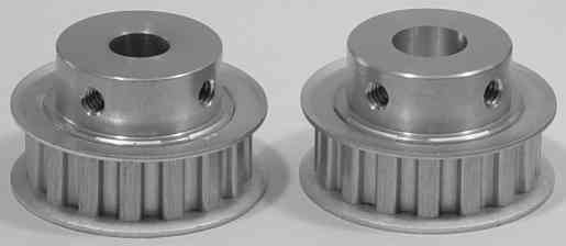
Figure 8 shows the aluminum timing pulleys. The one shown on the left has the original 1/2" bore. The one on the right shows how that stock hole is enlarged to 5/8" (bored on the minilathe with a boring bar) to match the motor shaft. Later, I bored the left pulley to 0.668" to match the end of the Y-axis screw. These are not the actual parts from the MSC catalog linked above, but some surplus items I found on eBay.
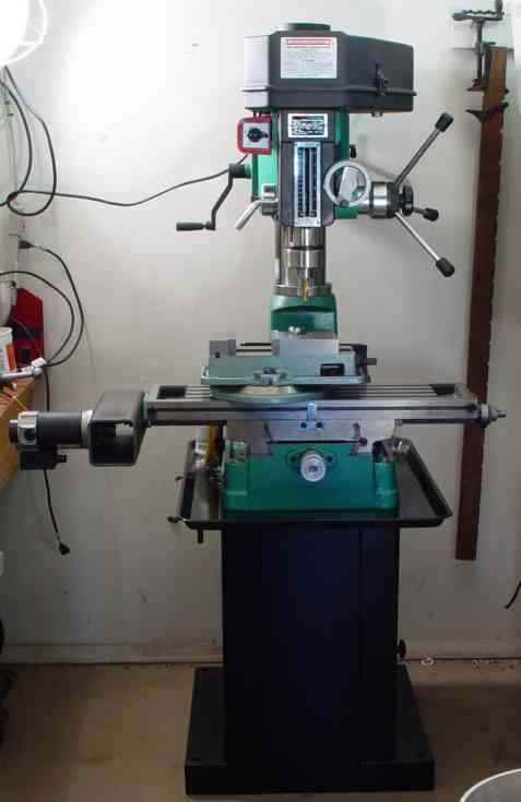
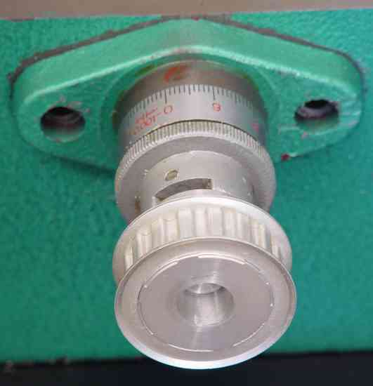
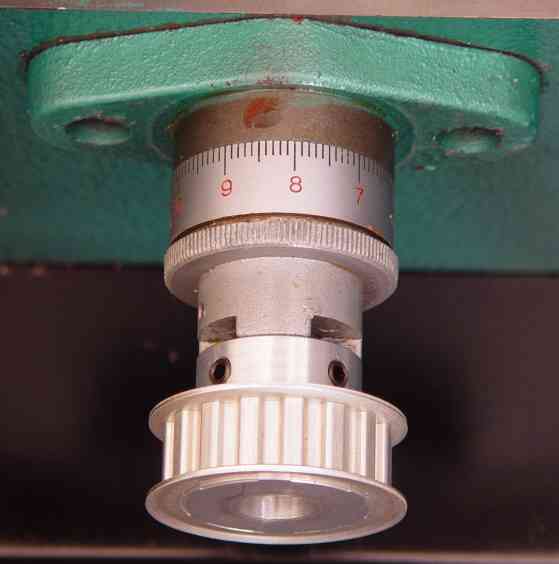
Figure 9 shows the mill-drill with the existing CNC X-axis on the left end of the table. The Y-axis has now been fitted with the re-bored driven timing pulley instead of the handwheel. Figures 10 and 11 show close-ups of the Y-axis timing pulley before mounting the motor.
Figures 12 through 14 show the X-axis CNC drive. It uses a significantly smaller (Simplatroll brushed PMDC motor, 24 VDC, 100 W ~= 1/8 hp, 5.5 A, 2000 rpm, 70 oz-in) servomotor than the Y-axis, a metric size with a 10mm shaft and what corresponds to about a NEMA 34 frame size. The X-axis mounting bracket uses the same principle as the Y-axis bracket, but uses 4" x 4" x 1/4" steel stock, the larger vertical dimension being required by the offset of the table mounting bracket. This mount was not a careful construction, but more of a "bootstrap" attempt to get something functional that I could use to create a better design. Reaching the mounting screws and bolts inside the channel is a struggle, which led to my design of cutting the 45-degree angle for the ends of the Y-axis bracket. The view of Figure 14 into the channel shows that the driving pulley is a 12L075 (12 teeth) while the driven pulley is a 16L050 (16 teeth), yielding a 12/16 = 3/4 geardown ratio to amplify the torque of the smaller motor. This is driven by a PC running MS-DOS and Dan Kowalczyk's TurboCNC (http://www.dakeng.com/) via a Geckdrive G320 DC servodrive (http://www.geckodrive.com).
This surplus motor was cheap because it used a Simplatroll quadrature encoder that had failed. I replaced the failed encoder with a Renco encoder, which I in turn had salvaged off a inexpensive surplus stepper motor that was too small to be much use. The old and new encoders required different shaft sizes (old 10mm, new 0.25"), so I bored and cut off the 10mm shaft to accept a short piece of 0.25" drill rod as an extension, held by cyanoacrylate glue, to mate to the new encoder. Thus, with a little tinkering (very educational in itself), I had a sturdy servomotor for about 1/10 the going price.
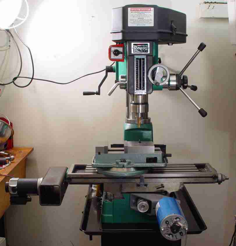
Figures 15 and 16 show the mill-drill, now with both X- and Y-axis motors mounted.
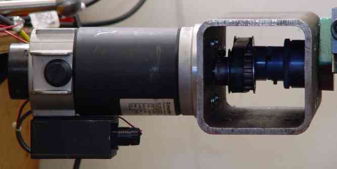
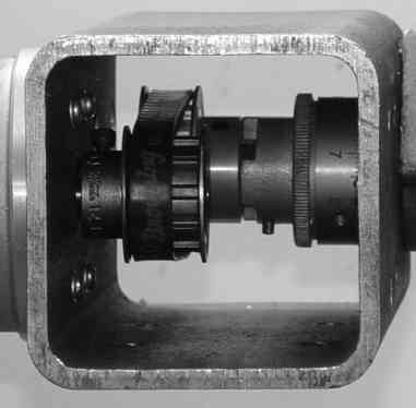
Figures 17 shows the view looking through the bracket from the right. You can see the two 16L050 aluminum timing pulleys, producing a 1:1 gear ratio. I slightly miscalculated the range of adjustment of the belt tension, so that the belt is still a little loose when adjusted all the way out. The bracket needs to be about 1/2" longer for this belt size. The next smaller belt size (135L050 instead of 150L050) stocked by MSC would decrease the pulley separation by 0.75 inches, which would be just about right. It is worth analyzing the belt geometry carefully before committing to cutting the bracket and buying the components. An idler wheel could make up for a too-long belt, while adding some traction to the pulleys.
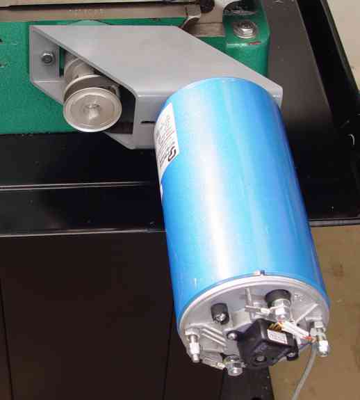
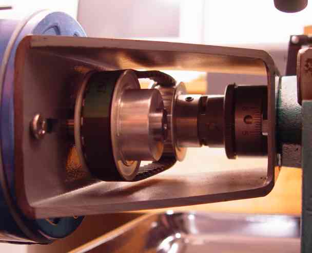
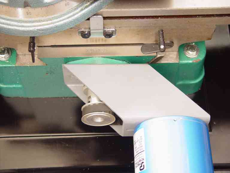
Figures 18 and 19 show close-ups of the bracket mounting on the Y-axis.
I now offer components and kits for my CNC conversion in various states of completion.
| Item | Description | Price | Buy Now |
| Y-bracket | The bare Y bracket shown above (cut from 3x4x0.180" rectangular steel channel, deburred, sandblasted, primed with Extend, no mounting holes). Ready for you to mill, drill, and spray-paint into a finished bracket custom-fitted for your machine. Order and remit via Paypal only. | $20/each + $8/shipping-handling. Free shipping on additional units. |