February, 2004.
June, 2006.
Using the CNC capability on the milling machine, I am experimenting with mechanisms for a simple movie film transport for my digital telecine project. I am starting with 16mm film size, with an eye to designing a mechanism easily scaled or converted to 8mm and 35mm film. I describe them below, starting with the most recent and continuing further into the past.
![]() This latest version incorporates a type of mechanism I observed on a commercial film transport
used to play the audio tracks from 16mm film.
I developed a CAD 3D solid model to redesign, visualize and actuate the mechanism in software.
The CAD model also allowed me to make mechanical drawings and automated tool paths for fabricating the parts in my CNC machine shop,
This latest version incorporates a type of mechanism I observed on a commercial film transport
used to play the audio tracks from 16mm film.
I developed a CAD 3D solid model to redesign, visualize and actuate the mechanism in software.
The CAD model also allowed me to make mechanical drawings and automated tool paths for fabricating the parts in my CNC machine shop,
Construction: The baseplate is a machined aluminum block, milled flat and precision drilled. The idler rollers are turned on a lathe from pure PTFE (Teflon) round stock. Each roller self-lubricates as a bearing on the cylindrical post and capture screw which projects from the baseplate. The central sprocket is the same 16mm item cannibalized from an old projector, as used in the previous prototypes. The sprocket is attached directly to the servomotor (Minertia brand, permanent-magnet, brush DC) shaft with a small aluminum bushing to adapt the inside diameter. The servomotor shaft output is controlled to 1/2000 of a revolution by a Geckodrive G320 controller (not shown) and PC. The tension idler is an aluminum arm with Teflon rollers, and maintains its force against the film from a small spring (not shown) stretched between the two brass hex nuts on the arm and baseplate, and ball bearing pivot attachment to the baseplate. The illuminator unit is an array of inexpensive LEDs backed by a custom printed circuit board. The LED array is housed in a UHMW-PE (ultra-high-molecular-weight polyethylene) which is an versatile structural material as well as an effective optical diffuser for the generated light. All these parts were fabricated on the Bridgeport milling machine or Logan lathe.
Film motion: To understand the film motion, first understand that the incoming film, being locked against the upper portion of the sprocket, and the outgoing film, being locked against the lower portion of the sprocket, moves synchronously in opposite directions at equal rates. This inherent synchronization maintains a moving loop of some fixed number of frames. Thus a single spocket and motor can maintain a stable film path, with an arbitrary loop size available to pass film over imaging components.
Film path: (See diagram below.) The film supply and take-up reels (not shown) are above and below the transport. The film path enters and leaves the transport to the right of the 4 rollers around the sprocket. The 2 rollers immediately above the sprocket lock the incoming film to the sprocket motion. From there the film moves under the tension roller, over and around the top left roller, past the illuminator, under and around the lower left roller, and locked to the sprocket motion again by the 2 rollers immediately below the sprocket.
Registration: The film path to the left of the sprocket is locked in a triangular loop of some number of frames, the number of frames being fixed when the film is manually threaded into the mechanism. The loop length of the mechanism is however a partial frame longer than what the tightest path (no slack) would impose, such that there is slack in the loop. The tension roller pushes against the early part of the loop, maintaining tension in the film as it passes in front of the illuminator. The illuminator surface incorporates a gate which aligns the film from side-to-side. The combination of rollers, tension, and gate maintains the film registration in all six degrees of freedom. The bearing posts for each roller incorporate an offset design which allows for mechanical adjustment and alignment. The illuminator attachment screws also allow for alignment to the film path.
Control: The servomotor positioning error is better than the random mechanical registration error, so the computer has effective motion control of the film to within the mechanical limits inherent to the transport.
Illumination: I am still experimenting with illumination. The LED illuminator is just a scaffold device, since it does not produce an precisely even illumination, and the spectrum of "white" LED light is actually a troublesome combination of various phosporescent colors, not unlike a fluorescent lamp. I foresee a unit for even illumination using a tungsten lamp, pair of aspheric condenser lenses, and Kohler illuminated light-shaping diffuser.
Capture (close-up): I am still experimenting with camera close-up optics to capture the illuminated film frames. I have designed and built a custom close-up lens attachment, consisting of paired equal achromat lenses, for my Sony DSC-F828 camera (8 megapixels) which magnifies a 16mm frame to nearly fill the camera field of view. By zooming to fill only a smaller central portion of the field of view, color aberration and pincushion distortion are minimal, at the expense of resolution, but the frame height still encompasses an excellent resolution for 16mm film (about 1000 pixels spanning the 0.3 inch frame height).
Capture (microscopic): I have also designed and built a custom photo eyepiece to couple the Sony DSC-F828 camera to the Bausch & Lomb Stereozoom inspection microscope. This gives ideal images with resolution down into the film grain, but the apparatus is bulky and expensive.
Benefits:
|
Disadvantages:
|
Film path, shown in red.
 This version works well as a basic transport.
It consists of three parts: a base, a guide "B", and a guide "C".
Originally the base and guide "B" were to be machined from a single billet of material,
but after botching the many steps in machining from a single billet, it occured to me that it would be simpler to make two
parts and hold them together with 1/4" stainless steel dowel pins (the pins make a firm but removeable
press-fit in the HDPE plastic).
This design adds a capture guide (guide "C") against
the sprocket, which keep the film engaged at all times to at least 4 sprocket pins.
The sprocket axle turns inside a close-fit through-hole in the plastic, with the plastic itself
serving as the bearing.
This version works well as a basic transport.
It consists of three parts: a base, a guide "B", and a guide "C".
Originally the base and guide "B" were to be machined from a single billet of material,
but after botching the many steps in machining from a single billet, it occured to me that it would be simpler to make two
parts and hold them together with 1/4" stainless steel dowel pins (the pins make a firm but removeable
press-fit in the HDPE plastic).
This design adds a capture guide (guide "C") against
the sprocket, which keep the film engaged at all times to at least 4 sprocket pins.
The sprocket axle turns inside a close-fit through-hole in the plastic, with the plastic itself
serving as the bearing.
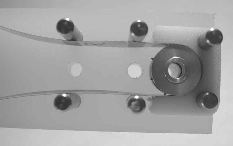
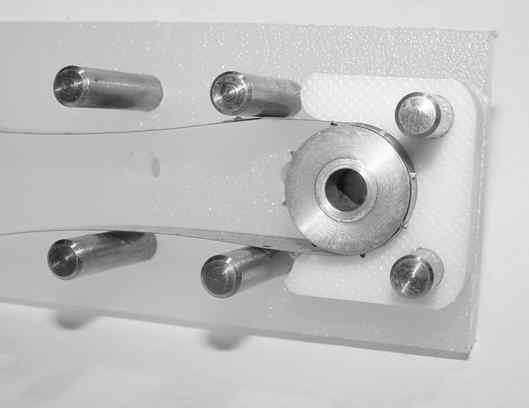
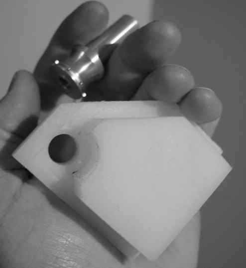
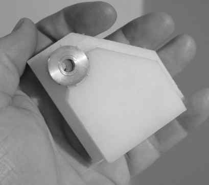
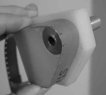
The photos show the assembly without guide "B" in place. Extra dowel pins serve as film guides. The film shown is just a strip of leader spliced into a loop to serve as a continuous test strip. Even without the guide "B" between the pins, the sprocket and guide "C" reliably capture and move the film. The film undergoes a frictional wipe against guide "C", which is similar to what is found in a typical projector; perhaps using a set of free rollers would minimize the wear for fragile film specimens.
See my handwritten design sketch and notes [60 KB PDF file]
for this design, which explain which parts are which, and how I converted the sketched designs
into G-code for the CNC milling machine. The milling machine cuts and drills the parts using 1/4" and
3/8" straight milling bits. Given that the most critical dimensions in the assembly require a
tolerance of a few 0.001", the stretch and bend of the plastic material under milling cutter forces must be managed
by a careful strategy for jigging, plunging, and cutting.
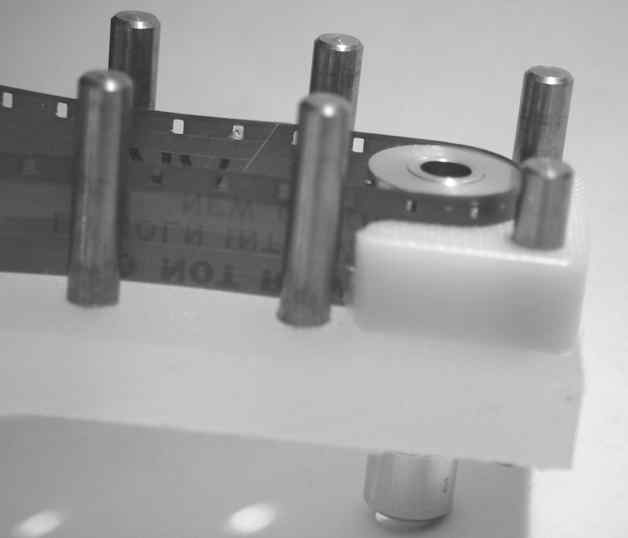
Since these photos were taken, I've added a PC-controlled servomotor to the sprocket, and mounted the sprocket assembly to a machined aluminum plate for a foundational base, somewhat like the costly optical prototyping plates. This servomotor alone is capable of real-time (18 fps) stop-motion of the film, or 35 ips fast feeding. I'm using a Minertia R01SAK0E with integral digital encoder, with a Geckodrive G320 driver.
I have been experimenting with the optical issues, with the transport providing the stage, and the digital camera free-standing above, viewing through the B&L inspection microscope. I am investigating white LEDs and Köhler condenser optical designs for frame illumination. The take-up/supply reeling issues remain to be solved; for now I am just using either a small test loop or hand-feeding reels.
I have also discussed pinch-roller/capstan transports and line-scanner imaging with Sheldon Epstein at k9ape.com.
 I designed the first attempt shown here to test the suitability of the
material in three aspects: (1) natural lubricity of the polyethylene
(UHMW-PE or HDPE) plastic for a film path, (2) natural lubricity and
strength of the plastic as an integral bearing for sprockets, and (3)
shape fidelity and precision of the process.
I designed the first attempt shown here to test the suitability of the
material in three aspects: (1) natural lubricity of the polyethylene
(UHMW-PE or HDPE) plastic for a film path, (2) natural lubricity and
strength of the plastic as an integral bearing for sprockets, and (3)
shape fidelity and precision of the process.
I cannibalized the sprocket in the photos from an old Bell and Howell
projector bought for next to nothing at a thrift store. The sprocket has
an aluminum body and shaft, with a steel sprocket wheel. Manufacturing
these sprockets out of metal seems inherently difficult, and indeed,
they are costly items to purchase, especially considering the ongoing
replacement of film with digital imaging.
I have studied a few movie film transports in the form of projectors, editors, and printers. Those various applications have different goals in terms of economy and performance. The designs typically date back to an era before modern plastics and CNC machining. I am still in a process of understanding the principles of film transport, in order to engineer an economical, precise, and reliable mechanism for stepping film frames through a digital telecine imager.
One principle of design is that the image area of the film should receive minimal contact, especially sliding contact. This is why sprockets have concave relief in the center, or are even simply pairs of star wheels with no center at all. The film path through the transport mechanism should ideally only touch the film in the sprocket area, and this contact should be in the form of a rolling member instead of a frictional slide.
Another principle is that the film must reliably engage the sprocket teeth. This in turn requires that the film either be in tension across the sprocket drum, or confined with guides to a path along the circumference of the sprocket. This requirement in turn implies some kind of frictional guide or roller confinement of the film. Frictional guides are undesirable, because they increase the force needed to move the film, and the engagement of sprocket teeth provides a strictly limited degree of force. Roller guides are thus preferable, both to eliminate frictional wear on the film itself, and to lower the force needed to keep the film moving. Increasing the number of teeth engaging the film improves registration and reliability, and increases the available force to move the film, because the force against the edges of the film sprocket holes is divided across the number of holes engaged. Larger sprocket wheels thus perform better, but are more expensive in themselves, and also more expensive in requiring a larger overall transport assembly.
Another principle is that, to avoid wear and stress on the film, the flexing of the film should be minimal, measured both as the maximum degree of curvature and the integrated change of curvature. That is, the film path should be as straight as possible, consistent with maintaining positional accuracy and engagement. The relation of film path curvature to film stress is a trade-off with the utility of curved paths for effective engagement mechanisms like sprocket wheels.
Note that the forced change of curvature with time applied the film constitutes the potentially damaging stress of wheel-sprocketing the film. In engaging film into and subsequently out of a sprocket wheel portion of the film path, the film undergoes an initial flex as it engages the wheel, followed by a final un-flex as it disengages. The time the film spends actually engaged around the sprocket wheel does not contribute additional stress to the film. So the stress of sprocketing does not depend on how far around the sprocket wheel the film engages; one might as well engage for a 180 degree U-turn to nearly maximize the number of sprocket teeth being engaged.
Sprockets need not be wheels, they can also be implemented as linear recirculating chains or belts (recall the tractor feed mechanisms once common on computer impact printers using continuous paper forms). Linear sprockets eliminate the stress of curved paths, while requiring more frictional or rolling contact opposite the traveling sprockets to maintain engagement. Linear sprockets are much more elaborate and costly mechanisms compared to simple sprocket wheels.
Other design considerations include the ease of threading the film into the mechanism, performance in the case of imperfect film (torn or plugged sprocket holes, splices, brittleness, shrinkage), effect of a malfunction or misfeed (e.g., loss of sprocket engagement, potential for new damage) on the film, reversability of the film transport direction, engagement to the supply, and provision for take-up reels. The design goals of a transport for digital telecine are not necessarily the same as for a projector.
This first prototype didn't work well, because it did not properly constrain the film against the sprocket. Thus, version 2.