
August, 2009.
This page describes what I call "Flatbed Scanner Digital Telecine" (FSDT), a process I am developing to inexpensively convert movie film to digital movies using ordinary flatbed scanners rather than exotic, expensive telecine converters. This page has mostly to do with the mechanical aspects of the project that acquire the scanned images. My most active efforts lately involve designing an inexpensive PC-controlled servomotor film transport, which is described on my page, Making a Movie Film Transport Mechanism, which is in turn based on my growing CNC machine shop. See also my page on my tiffcine software that post-processes scanned still images of movie film strips into digital movies.
The film industry term "telecine" is commonly used to describe converting movie film to any of various video formats. Commercial telecine is a costly process, involving specialized film scanners and video recorders, typically analog. This is not economical for the 50 feet of film I had to convert, since the minimum charge would be excessive. It is also increasingly out-of-date, as digital imaging on a PC has advanced to the point of being better and cheaper than any analog conversion process.
The essential tasks are to scan each frame of the film to create an ordered set of digital still images, and to assemble those images into a digital movie file. Each frame must be physically registered based on the sprocket hole (perforation) locations. Digital scanning allows us to apply correction for color, contrast, and other parameters to restore the aged film record.
Film scanning on a PC requires resolution of approximately 1600 to 2400 dpi to approach the full image granularity present in the film stock. This is based on a rough equivalence of the 7.5 mm by 10 mm frame size of 16mm film to VGA-resolution digital images of 640 by 480 pixels. Quite a few inexpensive 35mm film scanners are available for PCs that yield 2400 dpi resolution scans, but these are not suitable for 16mm movies. They are strongly oriented towards scanning single-frame 35mm slides or large-format negatives, and unable to handle long strips of 16mm film.
Since flatbed scanners with light boxes are available to scan large-format transparencies and film strips, I conceived the notion of a "poor man's" telecine using a flatbed scanner. The major limitation of applying inexpensive flatbed scanners to film scanning has been their limited spatial resolution, typically only 600 dpi, which is suitable for paper documents and photo prints, but not enough for film. Another concern is dynamic range, which in dedicated film scanners is typically 3.4D, but in flatbed scanners not even specified. Yet another issue is a technique to register and separate thousands of movie frames from digital film strip images.
In 2001, two flatbed scanners appeared on the market which renewed my interest in the FSDT process. The first was the Microtek 3750i, a flatbed scanner equipped with a 35mm filmstrip lighting adapter and costing only $70. Although limited to 600 dpi resolution, the 3750i was cheap enough to allow experimental trials of FSDT techniques. The second was the HP 7400c, a flatbed scanner equipped with 5 by 5 inch film lighting adapter and costing $500, but promising a remarkable 2400 dpi resolution. The 7400c promises to be the hardware which can make high-quality, low-cost FSDT possible.
In June, 2001, I bought a Microtek 3750i for experimentation. The "LightLid 35" device that comes with the scanner illuminates about a 1 by 6 inch area. One can simply put a strip of film on the scanner glass, place the LightLid on top of the film, and scan the film using the same software provided for reflective (paper) material. While the 600 dpi resolution is unsatisfying, using the preview histograms to characterize the film exposure and range allows you to bring out the full depth of color and constrast available in the film record.
In January 2002, I tried an HP PhotoSmart S20 film scanner, not so much as a practical way to scan movie film, but to get a better feel for the spatial resolution and dynamic range needed for film. I also experimented with digitally photographing movie frames with a digital still camera and microscope.
In February 2002, I acquired an old but working Bell and Howell model 173 movie projector, an exquisite piece of machinery from a bygone age. I'm busy tearing apart spockets and gates and shutters to see how one might build a film transport for the digital era. I take comfort in the certainty that all of Bell and Howell's patents embodied in this projector have long since expired. And I admit to actually projecting my archival film in the old-fashioned way, which after years of digital immersion is a very wistful and nostalgic experience.
In May 2002, I acquired a Sony DSC-F707 digital still camera which would seem to solve nearly all the imaging problems. With a 5.0 megapixel imager and a superb Zeiss lens that focuses as close as 2 cm distance, this remarkable camera has an effective close-up resolution of 1700 dpi! It would seem that this camera could directly shoot 16mm movie film frames at slightly better than 640 x 480 resolution. But there are several disadvantages. You are cropping out most of the still frame, and thus the data transferred from the camera is mostly discarded, effectively slowing the process beyond what it might otherwise achieve. The close-up depth-of-field is very narrow, and it may be impossible to achieve a flat focus across an entire frame (and taking several frames per shot would seem impossible). I know of no way to control the camera shutter through the USB interface; indeed when the camera is connected to the computer it completely leaves the picture-taking mode. While there is a remote shutter-release connector separate from the USB port on this camera, suggesting that a computer could at least take a sequence of still frames automatically before having to upload the image files, the Sony remote release gadget is $50 and may consist of more than just a simple switch contact.
To make a movie, the digital scan of the film strip must first be cut into frames. My design is to process the raw scanner images through a command-line utility program I wrote called tiffcine, which operates by (1) loading the bitmap image by reading a TIFF file, (2) finding the sprocket perforations through some simple pattern-recognition of the scan, (3) cutting out each frame and writing a sequence of separate still-frame TIFF images. A fourth step is then required to combine the sequence of still-frame image files into a digital movie format using a digital-video editor application. I took a mechanical gating approach to eliminate most rotational variations in the scans, which concentrated the software effort on detecting the perforations and generating the cropped images as TIFF files. I hope to update tiffcine to itself write a simple uncompressed RIFF (.AVI) movie file instead of depending on a separate digital-video editor. The uncompressed movie is easily converted to more efficient compressed formats using the excellent VirtualDub application.
Movie projectors and telecine scanners transport movie film through a "gate" which aligns the film and registers the sprocket locations. Rather than placing the movie film loosely on the flatbed scanner, I conceived of improvising a simple gate on the flatbed glass itself. I found that the ordinary materials of double-stick tape and blank transparency film could be used to cement a gate path onto the scanner glass. By carefully aligning the edges of this improvised gate to the scanner axis, the film is held in a repeatable location that requires no rotational deskewing. With some pen marks on the gate to indicate sprocket registration and strip length, I was able to calibrate a scanning area that covered the repeated strip placements and manually register the leading sprocket hole for each scan. Even using the rather clumsy scanning software provided with the Microtek scanner, I was able to advance the 50 feet of film and scan each strip in about an hour total.
|
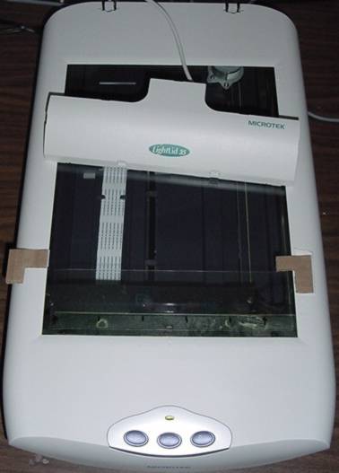
| The Microtek 3750i scanner set up for 16mm film scanning. Document lid is removed. Corners cut from corrugated cardboard are affixed with sticky foam tape to provide repeatable alignment for the LightLid. You can just see the strips of transparency film on the glass at the bottom of the photo. |
|
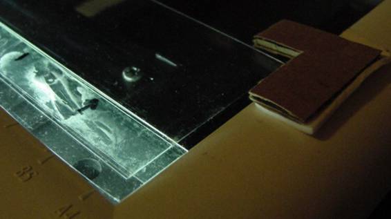
| Close up of the edge of the film gate. There are two layers of transparency material making up the the gate. The first layer is a narrower strip stuck on the glass with double-stick tape, carefully aligned with the scanner axis. The movie film edge rides along this narrower strip. Over the narrower strip is a second wider strip that just presses the film stock against the glass and holds it in position. I also used a third strip (not shown) against the opposing edge of the movie film, but this may not be needed. |
|
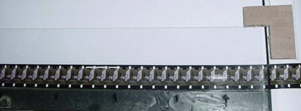
| Film strip in place in the gate. A sheet of white paper is under the film just to make it visible for this photo. Pen marks indicate various frame edges to keep track of where to manually advance each strip. Note that this piece of film has torn sprocket holes from clumsy projection many years ago. |
|
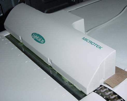
| In this photo the film stock and LightLid illuminator are in place. The alignment of the LightLid does not need to be nearly as precise as the film in the gate, since the lighted area is larger than the film strip, but the cardboard corners keep the unit from sliding around. |
|
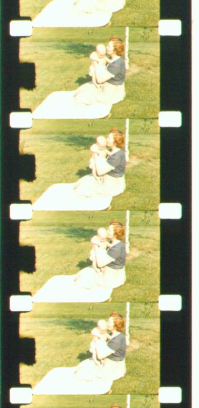
| A few sample frames scanned from the 16mm movie stock, which is 50-year-old Kodachrome film. The lighted scanning area on the Microtek 3750i is about 7 inches wide, so each strip could contain 24 complete movie frames, each 7.5 mm high. The scanner's 600 dpi resolution (somewhat worsened by JPEG compression of this sample image) does not recover the full details in the film stock. More expensive scanners like HP 7400c should have enough resolution to recover all the film's details. My motive for this project centers on my desire to preserve and view a short clip of 45-year-old 16mm movie film, which happens to be the only movie of me taken during my childhood. (The bald baby is me! And that's my mother holding me. June, 1956.) There are no other movies of me until video camcorders arrived in the 1980s. |
I wanted to prove the resolution limits of the analog film and how well the the flatbed scans and a film scanner approached that ultimate limit. To prove the analog film resolution, I digitally photographed a frame through a high-quality microscope. For comparison to a film scanner, I used an HP PhotoSmart S20 film scanner on several sample frames of my 16mm stock at 2400 pixels/inch. The HP film scanner, to my regret, while a fine device for its intended purposes, is not usable for continuous scanning of movie film because of its hardware and software design, which "gobbles" the film into a dead-end bed of about 6 inches maximum length, rather than feeding the film into a pass-through mechanism. The only way I was able to feed 16mm film in at all was by taping it to a strip of clear 35mm film.
I was annoyed by the way HP dumbed-down the TWAIN film scanning software for the S20, such that it permits only previewing and scanning of single 35mm slides or single frames from 35mm strips; furthermore, all the Windows user-interface standards are discarded in favor of a gimmicky set of buttons and sounds reminiscent of Microsoft's tawdry Picture-It. I was sad to see such a fine piece of scanning hardware needlessly limited in mechanical design and software. The S20 could easily be configured to pass through movie film strips of arbitrary length and scan them continuosly. Call me, HP!
Comparison of the 600 pixel/inch flatbed scan versus the film scanner shows that the flatbed resolution is far from adequate.

|
|
Tiny portion (0.050 by 0.038 inches) of a 16mm film frame
photographed with a Sony DSC-S30 1.3 megapixel digital
camera through a 30X Bausch and Lomb inspection microscope.
The combination of microscopic magnification and camera zoom
yields an effective resolution of about 7200 pixels/inch,
enough to bring out the film grain and surely capture all the analog image resolution.
Note how the analog grain renders shading, such as the gradients of the lady's cheek
or the fontanel on the baby's head.
The image is scaled here in the browser by 4/3 to match the size of the comparison images below. Dust appears white because this photo used reflected light from a white base under the film, which also inadvertently included reflected light off the surface of the film. I should have used a light box (such as the LightLid) to properly illuminate the film for this microphotograph, but I did not have one handy. Although the poor illumination does not render the colors well, the spatial resolution is adequately sampled. The digital camera and this microscope work so well together, that they suggest another inexpensive means by which movie film could be digitized in high quality. At 10X magnification, the field of view of the microscope is adequate to view a whole 16mm movie film frame in the unzoomed view of the camera, with the frame itself covering about 800 x 600 camera pixels. A film stepper could register each frame under the microscope using a similar technique to what I propose for the flatbed scanning. The exposure could be automatically taken in the digital camera and transferred to the computer using control methods implemented in the interface of certain Kodak models. One could play with the trade-off of the complexity of mechanical film advancing and registration, versus software which registered and extracted frames. |

|
|
Same film frame and crop as above, but scanned at
2400 pixels/inch by the HP PhotoSmart S20 film scanner.
Enlarged by a factor of 4 (unaliased) to set forth the pixelated image,
which is most prominent in areas of highest intensity gradient, such
as the transition of the lady's hair to cheek, or the shadows of the baby's eyes.
By comparing to the microphotograph, it is apparent that this film scanner is
doing a thorough job of capturing the film image in all its detail.
Dust artifacts on the image are mostly not on the film but on a clear carrier I was forced to improvise to trick the film scanner into thinking the 16mm film was 35mm. Dust appears dark because this is a transmission scan. Note the that dust fiber on the upper right edge resolves to 1 or 2 pixels across; this approaches the Nyquist limit, proving that the digital samples genuinely resolve at that spatial frequency. Merely interpolated resolution would have produced a more blurry image of the dust fiber. |

|
|
Same film frame and crop again, but scanned at
600 pixels/inch by the Microtek flatbed scanner.
Enlarged by a factor of 16 (unaliased) to set forth the pixelated image
at the same size as the other images above.
The colors are garish because of the way I used the Microtek TWAIN interface
to adjust the scanner exposure to fit film's characteristics, and thereby obtain
better density resolution; one can always
calm down this response in post-processing to render the colors in a more
conventional appearance.
The high spatial frequency of the pixel transitions are a form of periodic noise which make this image look worse than it should. It looks much better if you apply an optical low-pass spatial filter, which is to say, squint at it! Squinting stops down the lens aperture of your eye, reducing your visual resolution, thus smoothing the pixel transitions, much like anti-aliasing algorithms in digital photo editors. This lets you see the "image behind the image". |
It is interesting to compare all this hobby experimentation with the practices of the real film-making industry. See Kodak's resolution chart for their Cinesite movie film scanning service. The Cinesite machines are custom-made devices that incorporate such technologies as cool fiber-optic illumination and ultrasonic film cleaning, in addition to the more mundane tilm transport and optics designs. They consider 4096 pixels/inch to be the highest quality scanning resolution, and offer service at one-half and one-quarter that resolution. For example, 16mm film scanning is offered at 1712 x 1240, 856 x 620, and 428 x 310 pixels. That is, inexpensive desktop technology for movie film scanning is still below the highest professional standards of resolution and depth, but not for long.
I have also manually cut and assembled frames from the strips into movie clips of several seconds. This is a simple process, albeit tedious, in Corel Photo-Paint.
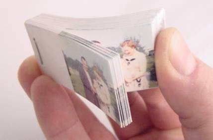
I also enjoyed the old trick, with new technology, of making a flip-book. Using Corel Photo-Paint, I printed strips of 10 frames at 1 inch height per frame on photo paper with a color printer, sliced up the paper frames with a print trimmer, and stapled them together into a book, 50 frames total. The kids love it and it gives them a good intuition of how movies and animation work, since VCRs, DVDs, and AVIs that they are familiar with don't give you a tactile product like the old film projectors did.
|
| A 50-frame flip book cut and bound from photo paper prints on a color inkjet printer. This is a fascinating, retro novelty. Everyone who sees it can't stop playing with it. |
Let's consider further the digital image processing involved in automatically registering the frame locations in a given scan of movie film, either through software, or mechanical gating, or a combination of both.
We assume that the film is flat against the glass and that the scanning array itself is square and linear. We also assume that the piece of film being scanned has parallel edges and regularly-spaced sprocket holes. We define also the coordinate system of the scan such that the film image is in the first quadrant, with the lower left corner near the origin, and advancing frames in the sequence starting at the highest Y coordinates and progressing down the Y direction. We number the frames of interest in a given scan starting from frame 0 at the top. Since 16mm film has four sprocket holes around each frame, we number the sprocket holes for each frame starting with sprocket hole 0 on the lower left of the frame image, and progressing counter-clockwise around the frame to sprocket holes 1 (lower right), 2 (upper right), and 3 (upper left). Let the vertical frame interval (equal to the vertical sprocket hole interval) be Y_s.
The registration problem for a given scan is to determine the number of frames in the scan, plus a 2-dimensional registration transform comprising three numbers, which we will call X, Y, and Theta, each in units of pixels. In the general case, each frame in a scan has its own registration transform. Theta represents the rotational skew of the film, implying an initial correction of Theta degrees counter-clockwise being required to align the long edge of the film on the Y axis. In terms of a 2-dimensional transform, Theta is applied first. (2) X represents the left-right movement needed to bring the left long edge of the film to the Y-axis. (3) Y represents the up-down movement needed to bring the center of the sprocket hole 0 of frame 0 to the X-axis for a given frame. Given our assumptions of flatness and regularity, for a given scan Theta and X are constant for all the frames, while Y increments by the frame spacing interval on the film. Thus the three values Theta, X and Y are sufficient to register all frames in a scan.
Consider first the simplest registration case where a mechanical gate aligns the film in the scanner and the initial sprocket hole is manually registered to a mark in the gate. In this case, we may assume that all the registration values are constant. The number of frames is constant because we calibrated a fixed scanning area to the gate dimensions. Theta is zero because we carefully aligned the mechanical gate edge to be parallel to the scanner's axis. X and Y are identical, constant values from scan to scan, which we can measure and characterize by examining several scans in an image editor. In this case we know a priori how many frames are in each scan, and we know the coordinates of each frame. No registration is needed.
Consider next the registration case using the same mechanical gate to align the film for Theta and X, but where we want to only coarsely advance the film without bothering to manually register the leading sprocket hole. This would be case for quick hand advancing of film, or if we used some simple mechanical advancer such as a stepper motor. Thus for each scan we need to determine the Y value by some sort of pattern recognition applied to the scan. Inspection of the film scans shows that the left column of sprocket holes is mixed vertically in the scene exposure area, while the right column of sprocket holes punctuates a black (unexposed) film area, providing a reliably high-contrast pattern.
To recognize sprocket perforations in the image, we are only concerned about finding an average Y value of the leading edges, and not the X location (but note below the important correction to this assumption). The mechanical gating aligns the right column of sprocket holes to fall in a known range of X coordinates that we may find by inspecting the film strip images. The film advance is also roughly registered, so that the key perforation for the first frame in a strip is within half a frame interval of some nominal Y location that is known. Thus we may apply the following simple 1-dimensional convolution algorithm to find a Y correction to the nominal Y.
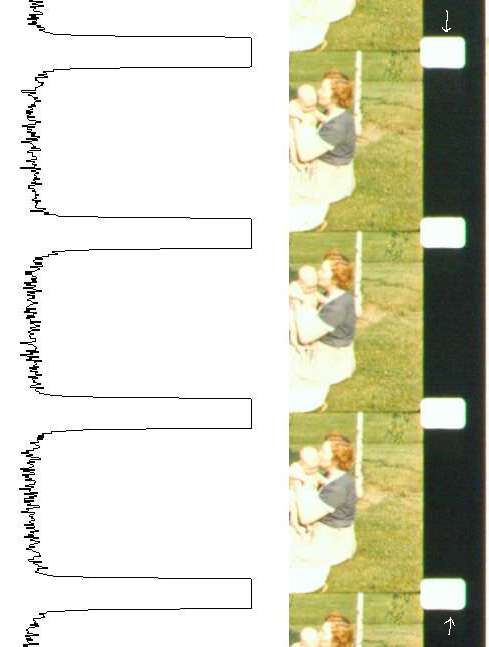
Take the vertical strip of pixels along the X coordinate underlying the centers of the right sprocket hole column. Apply a contrast-enhancement threshold to set each pixel to white or black according to whether the sprocket hole is present or absent. This strip now constitutes a bit vector, which shows a square-wave pattern of a black field (representing the unexposed film base) with narrow plateaus (representing the sprocket holes). Of course there will be some noise, distortion, and jitter, which we depend on the correlation to average out. To this bit vector we can correlate a "negative ideal sprocket pattern" as follows to locate the Y correction. We correlate the "negative ideal sprocket pattern" consisting of white and black pixels in an inverse intensity from what we would expect from a perfect sprocket pattern. The correlation operation is simply to sum the bit weight of the XOR of the two vectors, with a varying offset applied from 0 to Y_s-1. The offset yielding the maximal correlated weight yields the correction needed to bring the average frame into Y alignment.
The time to compute this correlation, being proportional to the square of the number of pixels in the correlated strips, might seem to be too slow. However, tiffcine correlates a pixel slice from only the single leading frame, not the whole scan strip, thus making the operation a small portion of the per-frame processing. Once the perforation for the leading frame is detected through correlation, the rough position of the next frame's perforation is known, and the same single-frame correlation is applied. In this way each perforation is independently detected. Correlating the entire strip at once is also of little value, since the locations of the perforations in the scan are, in practice, distorted progressively down the strip; correlating each perforation separately compensates for such distortions and keeps them from accumulating.
The image processing methods must compensate for the fact that the scanner introduces dimensional distortions. After using tiffcine on some sample scans, it became apparent that the scans incorporate a slight but progressive misalignment in the X (narrow) direction. This arises from physical gaps in the gate mechanism, and more significantly, from optical distortions in the scanner itself that vary across the scanning bed. The result is a "weave" in the movie playback that moves the framing left and right a few pixels on a cycle corresponding to the frames per scanned film strip. To compensate, I plan to add a further software registration step that, once the vertical perforation edge is detected, further locates the corresponding horizontal perforation edge.
Most film formats do not follow the single perforation-per-frame design of 16mm film. For example, 35mm film uses a closer interval for perforations, such as the 4 performations per frame of the 1.85:1 theatrical format. This requires a slightly more complex application of the same correlation methods to recognize a given number of perforations per frame. Furthermore, some method is needed to detect the perforation phase relative to the frame boundaries. This might be detected from (1) manual registration in the threading of the film, (2) from SMPTE standard framing marks in the perforation regions, or (3) from image analysis to detect a gap or discontinuity between frames in the image area.
|
| Grayscale intensity of a vertical pixel column through the center of the right sprocket hole column. Column taken from between arrows indicated. Good contrast and sharp definition allows accurate pattern recognition of sprocket hole registration. Correlating the inverted ideal sprocket pattern against the pixel column yields a minimum at the desired Y offset. |