Repairing the Whirlpool and KitchenAid Ice Machines
Inevitable Problems and How To Fix Them
Do It Yourself
OR
Know What Your Service Technician Should Be Doing
Where to Find Parts and How Much They Should Cost
Detailed Instructions Below on Troubleshooting, Diagnosis, and Repair
Written by a fan and aficionado of these machines.
My most recent update to this page was July, 2025.
The do-it-yourself parts and mail-in services I offer below are currently available;
I am still actively engaged in this business.
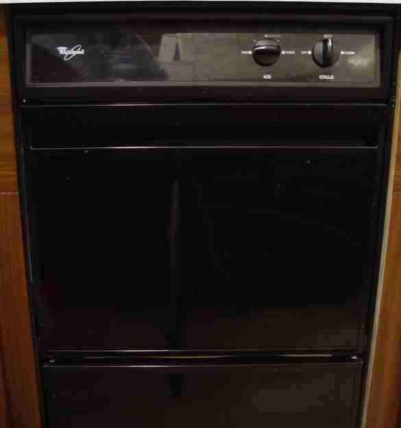 The under-counter Whirlpool ice machine is a stand-alone $2000 appliance which makes gourmet
clear ice such as for a wet bar.
It has been labeled and sold as KitchenAid, GE (General Electric), Sub Zero, Scotsman, Viking, Estate, GM/Frigidaire, Maytag, Amana, Roper, Inglis, Ross Temp, Marvel, and Sears Kenmore brands, and is similar
in quality and specifications to the under-counter Jenn-Air 50 lb/day ice machines currently sold.
This luxury ice machine should not be confused with the ordinary ice maker that is part of
a refrigerator-freezer; the former magnificent engine makes crystal-clear, flavor-free, ice cubes.
A refrigerator-freezer ice maker produces cloudy ice in a stale-garlic flavor, typically in odd crescent shapes,
and stuck together.
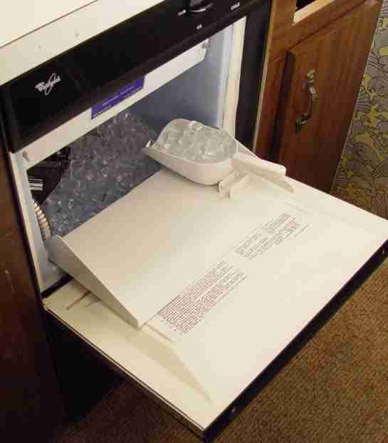
The ice machine's product is clear, pure, flavorless ice cubes which are luxuriously wet and loose, like a handful
of flawless diamonds scooped from a mountain spring.
Owning this machine once in your life will spoil you, like many of my correspondents who say they will never
again return to refrigerator ice. Among life's material joys and comforts, the little cubelets are both innocent and enduring.
The under-counter Whirlpool ice machine is a stand-alone $2000 appliance which makes gourmet
clear ice such as for a wet bar.
It has been labeled and sold as KitchenAid, GE (General Electric), Sub Zero, Scotsman, Viking, Estate, GM/Frigidaire, Maytag, Amana, Roper, Inglis, Ross Temp, Marvel, and Sears Kenmore brands, and is similar
in quality and specifications to the under-counter Jenn-Air 50 lb/day ice machines currently sold.
This luxury ice machine should not be confused with the ordinary ice maker that is part of
a refrigerator-freezer; the former magnificent engine makes crystal-clear, flavor-free, ice cubes.
A refrigerator-freezer ice maker produces cloudy ice in a stale-garlic flavor, typically in odd crescent shapes,
and stuck together.
The ice machine's product is clear, pure, flavorless ice cubes which are luxuriously wet and loose, like a handful
of flawless diamonds scooped from a mountain spring.
Owning this machine once in your life will spoil you, like many of my correspondents who say they will never
again return to refrigerator ice. Among life's material joys and comforts, the little cubelets are both innocent and enduring.
Besides this delicious indulgence, the ice machine also makes an excellent source for controlled cold-plate chilling necessary to the
operation of an even greater luxury, the home soda fountain (see my page on home carbonation).
On this page, however, we are only concerned with the ice and how to keep the machine running.
This residential ice machine creates 8 x 7 x 1/2 inch slabs of ice by recirculating
water over a metal evaporator plate chilled by an R-134a chiller (or R-12 before
the early 1990s; this basic machine design goes back to the 1950s). When a slab of ice reaches the finished thickness, a thermostat
triggers the harvest cycle, which reverses the chiller to warm the evaporator plate,
until the ice slab slides onto a cutter grid. The cutter grid consists of nickel-chromium ("Nichrome" is
one brand) resistance wire which is warmed by a low-voltage electric current.
The ice slab rests on the heated wires, and the wires slice through the slab, first in one direction on the
top layer of wires, then the perpendicular direction on the lower layer, yielding cubes of ice which drop
into an insulated ice supply bin.
The original machines were produced in an 18-inch width for a standard 34.5-inch under-counter height.
Since 1999 a 15-inch version is also available.
The only part of this machine which chills is the evaporator plate at the top of the machine where the ice forms.
Unlike a conventional refrigerator-freezer, the ice storage bin is only insulated.
The air inside is not refrigerated, and the temperature never drops below freezing.
This bin is more or less like a portable ice chest but built into the cabinet.
This is an essential principle of a wet ice machine.
The cubes stay loose and are always slowly melting, so the machine runs to make new ice to keep the bin filled and
to make up the ice you withdraw for use.
|
 I got to know these machines quite well over the last 24 years.
In 1995 I moved into a home equipped with one, and learned about this unusual appliance by doing my own repairs.
It eventually became an essential part of my home carbonation and soda fountain efforts (see link above).
I got to know these machines quite well over the last 24 years.
In 1995 I moved into a home equipped with one, and learned about this unusual appliance by doing my own repairs.
It eventually became an essential part of my home carbonation and soda fountain efforts (see link above).
Then in 2002, I wound up owning a truckload of them, after
I went to the bankruptcy auction of the infamous Enron accounting firm,
Arthur Andersen, where I had expected
to buy various assets for my computer business.
Their corporate skyscraper suites were furnished with a large quantity of these machines, recently purchased.
While I wanted to buy one to have as a spare, the auctioneer abruptly insisted on selling all of them as one lot.
Of course, nobody else at a business-equipment auction wanted such a haul, but I saw an opportunity, knew what I was dealing with,
and took them all for 5 cents on the dollar.
I made a handsome profit reselling them one-at-a-time on eBay (sorry, they're all gone now), but in the process I
had to become expert at diagnosing and repairing them, using my background as an engineer by profession.
This field experience provided a conclusive demonstration of what were the most common repair problems,
which led me to create this Web page for the benefit of fellow ice machine owners.
Having maintained this Web page for some years, I have corresponded personally with thousands of other ice machine owners, and
performed (or at least consulted on) all of the repair problems presented by these machines.
Below you will find the accumulated wisdom for diagnosis and repair procedures, obtaining original parts,
improvising ersatz parts, and dealing with hired service technicians.
The photos here show my personal unit made in 1997, model EC5100XFB0.
The essentially identical machine has been sold for years and years under a variety of brands,
model numbers, and styles of decor.
Other than a change away from R-12 refrigerant to R-134a about 1992, and a change from electromechanical
controls to computerized electronics about 2002, the principles, components, and physical arrangement have
been the same for many decades.
An excellent source of information, including parts diagrams, parts catalog,
and pricing is available at partselect.com
and at sears.com, even if they're not the best place to buy parts.
You can enter your specific model number there and compare the parts involved in your repair
to those specified for mine.
Similar models include:
ACS50
ACS501
ACS502
CCS51AEL
CECS2AE1
CHCS51AE1
CSWE1 CSW1AE CSW1AE1B5 CSW45 CSW45PA1B0 (Scotsman)
EC5100
EC5100XEB0
EC5100XEB1
EC5100XEN0
EC5100XEN1
EC5100XEW0
EC5100XEW1
EC5100XFB0
EC5100XFB1
EC5100XFN0
EC5100XFN1
EC5100XFW0
EC5100XFW1
EC5100XL
EC5100XP
EC5100XT
EC5100XT1
EC510BXD0
EC510NXD0
EC510WXD0
EC510WXE0
ECB5100XFB
EHC511
EUC050A1
ZDI15
ZDI15CBB
GI1500PHB0
GI1500PHB3
GI1500PHB6
GI1500PHW0
GI1500PHW3
GI1500XH
GI1500XHB0
GI1500XHB1
GI1500XHB2
GI1500XHB3
GI1500XHN0
GI1500XHN1
GI1500XHN2
GI1500XHN3
GI1500XHS0
GI1500XHS1
GI1500XHS2
GI1500XHS3
GI1500XHT1
GI1500XHT2
GI1500XHT3
GI1500XHW0
GI1500XHW1
GI1500XHW2
GI1500XHW3
GI1500XHW7
GI15NDXTB
GI15NDXTS
GI15NDXXS
GI15NFLTS0
GI15NFRTB0
GI15NFRTB1
GI15NFRTB2
GI15NFRTB3
GI15NFRTB4
IACS501
IACS50E1
IM30
JEAC501
JEAC50SL0
JEAC50SL1
JEACS50SL0
JEACS50SL1
JLAIC5053
JT051CAE1612
JT051CAE2511
JT051CAE2512
JVGC535A0
JVGC535A1
JVGC535W2
KUIA15NLH
KUIA15NRH
KUIA15NRHS9
KUIA15PLL
KUIA15PRL
KUIA15RRL
KUIA18NNJ
KUIA18NNJS5
KUIA18PNL
KUIA18PNLS1
KUIC15
KUIC15NRTS0
KUIC18
KUIS155H
KUIS155HLS3
KUIS155HRS3
KUIS15NNZW0
KUIS15NNZB0
KUIS15NRH
KUIS15PRH
KUIS185FBS0
KUIS185J
KUIS185JSS0
KUIS185JWH2
KUIS18NNJ
KUIS18NNJW5
KUIS18NNTW1
KUIS18PNJ
KUIV18NNM
MA15CL
MIM1555ZRS0
ML15CL
ML15CLG
ML15CP
ML15CPG
O53CAE1610
O53CAE1612
RC-50-SC (Ross Temp)
VUIM153DRSS (Viking Range Corporation)
ZD115CBBE
ZDIC150EBB
ZDIS150
ZDIS150WBB
ZDIS150WSS
ZDIS150WWW
ZDIS15CSS (GE Monogram)
198.887482
106.86482690
106.86482691
198.8814831
3KUIS185V0
235S0
501-ISC (SubZero)
JIM1550ARW
JIM158XBRS
JIM158XBRSO (Jenn-Air)
My trusty unit shown at left is still running after all these years.
I have had to: repair the grid several times, replace the harvest thermostat
with an electronic timer, replace the water solenoid valve, and recharge the unit
with refrigerant. The basic refrigeration mechanism is very sturdy and reliable.
Other owners of these machines have 30-year-old specimens still running.
|
Before you go off ordering expensive parts, or rashly discarding a failed unit,
see if my information below can't help you diagnose and repair the trouble more economically.
Let's first discuss the three most common problems that likely brought you here in the first place.
After that, we'll detail the universe of rarer problems.
As wonderful as this machine performs,
there are three chronic problems with Whirlpool's otherwise excellent design
resulting in very costly repair calls, typically after only a few years of constant operation:
- The rather thin wire in the cutter grid
breaks.
The result is that the slabs of ice back up in the machine and no ice cubes are cut to fall into the supply bin.
- On pre-2002 machines with electromechanical controls, the solder joint bonding the harvest thermostat to the evaporator plate cracks and breaks loose,
due to repeated infiltration and expansion of water in the freeze-thaw cycles.
The thermostat no longer senses the actual temperature of the evaporator plate, and takes longer to trigger
a harvest cycle.
The repeated cycles of icing slowly push the bracket holding the capillary tube farther and farther away
from the evaporator plate.
The intervals of harvesting become longer and longer, despite the manual adjustment to the
thickness setting that should make the cycles shorter.
Eventually the machine will not trigger a harvest cycle at all, and one thick slab of ice sits on the evaporator
plate, never to be harvested, and no ice is produced in the supply bin.
- The solenoid valve that controls water flow to the reservoir fails in one of two ways.
One, it may fail to close completely, resulting in a continuous trickle of warm water into the reservoir, which
at first slows ice production, and eventually stops ice production altogether if it gets bad enough.
Two, it may fail to open fully or at all, so that the reservoir never fills, and only thin ice slabs, or no ice at all,
is produced.
Not only do these problems suggest a house call from an appliance service, but these service calls can
be very expensive. Ice machines are relatively rare items, and the expertise to diagnose and repair them
tends to command a premium price, as do the manufacturer's sole-source parts.
More typically, you're likely to get someone who may know how to fix a common refrigerator, but
doesn't understand ice machines well enough to diagnose their unique types of problems.
If you're like me, you may find that you can perform a costly repair yourself, at minimal expense.
What you need is some information and diagnostic analysis, which is why I wrote this Web page.
Some repairs I'll describe may be beyond your abilities, but even if you're not a do-it-yourself'er,
you can use this information to make a firm diagnosis yourself.
At the very least, you will be able to critique whether a service technician is giving you a correct diagnosis and
a fair price for repairs. In the grim case where your machine is not worth fixing,
you can decide this without having to pay for a service call.
I have published this information as part of my machine shop pages,
because these repairs have to do with metal itself (nickel-chromium wire, solder), or with parts
or suppliers closely associated with metalworking, even though there is
no actual machining involved.
Understanding the Unit via Service Manuals
Before you attempt to diagnose or repair a problem, you may wish to study some of the service manuals I've been
able to collect over the years. Different manuals cover the various designs and models from the 1970s to the present, so
pick the manual(s) with the closest match to the type of machine you have.
If you're not sure what is the closest, the KitchenAid KAR manuals are the best technical reference manuals, as they
cover all technical details and diagnostic procedures for the basic Whirlpool machine, which what all the brands
(Whirlpool, KitchenAid, GE Monogram, Jenn-Air, Maytag, etc.) are actually built from.
- The Service and Wiring Sheet 2180831 (46KB PDF file) describes
later versions of the older electromechanical-controls machine (EC5100 series, manufactured up until about 1999 and
sold by appliance dealers for a few years thereafter).
The Tech Sheet 758860-E and 758846-C (167KB PDF file) describes the earliest models.
The earliest models used the spring-clip type cutter grid described below, and described in the
Whirlpool repair parts list for EC5100XP models.
- The later version of the machine, introduced in 1999, uses an electronic printed circuit board instead of electromechanical controls;
this was a fundamental change in the design which must be considered in diagnosis and troubleshooting.
Nearly all working machines today are of this electronic design.
Working electromechanical machines are becoming rare as they age
into necessary repairs, typically demanding orphaned parts like thermostats that are hard to find.
The recent version of the electronically-controlled Whirlpool (and KitchenAid branded) machine (2007 and after) is described by
Service and Wiring Sheet 2324311C.
The very first version of electronic control models (starting 1999)
were described by the Service and Wiring Sheet 2217233-REL and 2217235-REL (224KB PDF file).
A later version (2005) which seems to have the same information is Service and Wiring Sheet 2313728-REL.
- The GE Monogram series (ZDIS150) has a similar Technical Data sheet 162D9144P005 (part numbers 2217278 or 31-51316-1),
and the Technical Service Guide (part number 31-9196, March 2010) for all ZDIS150 models (including ZDIS150WSS, ZDIS150WBB, ZDIS150WWW; these
three-letter suffixes on the ZDIS150 model code just indicate the color decor of white, black, or stainless).
This GE branded machine appears to actually have been made by Whirlpool.
These manuals are well-written but not as thorough as KitchenAid's KAR manuals, so it may be necessary to study them both to get a full understanding.
- If you have the newer electronic controls,
read these key sections of the service manual for the Whirlpool GI1500 series ice machine (384KB PDF file, 34 pages), which
includes wiring diagrams. The theory of operation and troubleshooting information is worth reading to understand older models as well.
Also see the parts diagrams.
The manuals cover the KitchenAid brand versions of the Whirlpool machine.
Here also is the owner's manual use and care guide.
The KitchenAid models are designated KUIS155 and KUIS185 with suffixes for variations in finish style.
- Various versions of the electronic control board (part numbers 2185947, 6100499, 2304016) have slightly different timing in the run sequence chart [1-page PDF file].
- Whirlpool Instruction Sheet 4388700 Rev A 6/04 (view that document [2-page PDF file])
which details an update to the
electronic controls released in 2004. The older PC board was Whirlpool part number 2185947.
Updated boards are Whirlpool part numbers 6100499 and the most recent 2304016.
The update improves the cycle timing and diagnostic sequence,
and provides flashing LED trouble codes when the controller detect faults in the machine.
The latest version, Whirlpool 2304016, differs from Whirlpool 6100499 in adding numerous intelligent features:
a delay of 30 seconds at initial power-up
before starting the compressor, a minimum/maximum freezing time of 15 to 25 minutes, 1 minute maximum water refill time,
forced 25-minute freeze with 4-minute harvest timed cycle time if you disconnect the evaporator thermistor,
forced shutdown with half-second flashing LED if thermistor-controlled harvest time exceeds 16 minutes,
forced shutdown with one-second flashing LED if the bin thermistor fails,
and diagnostic flash codes for thermistor tests are generated when running the cleaning cycle (see the manual for details).
So the detected faults in these later models include a too-long harvest cycle, and a failed bin or evaporator thermistor.
- See also my detailed parts diagrams and catalog for the older
electromechanical machines, and compare them to your unit.
- KitchenAid KAR-19 technical education job aid 4317408 document [5 MB PDF file, 74 pages],
for the "2007 Design" version of the KitchenAid branded machines manufactured by Whirlpool.
This is a training manual for service
technicians working on ice machines. Much of it just repeats what is in the service manual specific to a given model,
but there are detailed procedures for replacing all the components in the general machine.
An older version of this manual for design years from 1999 to 2007
is the KitchenAid KAR-14 technical education job aid 4317339 document [large 60 MB PDF file, 80 pages].
Find the design year of your KitchenAid model by the ninth letter in the model number:
H=1999, J=2000, K=2001, L=2002, M=2003, S=2006, T=2007 (etc).
Find the year of production in the second letter in the serial number: M=2002, P=2003, R=2004, T=2006, U=2007 (etc);
the third and fourth digits indicate the week of production.
The corresponding Whirlpool model numbers for the 2007 design update seem to be the GI15NFRTB pattern.
(The chief feature introduced newly into the 2007 design was a drain pump with water level sensor in the reservoir; this allows
the control board to exert powered control over both filling and draining of the reservoir, thus improving the reservoir water freshness,
reducing the amount of water required to refill, and detecting mechanical problems with filling and draining.
The fill valve also meters the incoming water flow rate, containing its own complicated electronic circuit board to do so.
Harvesting apparently triggers not just from evaporator thermistor temperature, but also from low water in the reservoir.
While this newer gadgetry improves performance and efficiency, it makes for more things to possibly go wrong, complicates diagnosis and repair,
and requires expensive manufacturer-specific parts to replace anything that fails.)
The 2007 and later Whirlpool or KitchenAid machines come with two brief service documents tucked into the chassis: the
KitchenAid KUIC18PNTS2 Diagnostic Procedure and
the KitchenAid W10217947A Service Sheet.
Some KUIS18 units came with the Whirlpool W10206442E Service and Wiring Sheet.
- Jenn-Air JIM158XBRS models Service and Wiring Sheet.
- Marvel IM30 service data sheet [PDF file, 2 pages] and service manual [PDF file, 35 pages].
This model is not the Whirlpool type, but similar in principle,
with good instruction in the theory of operation and diagnosis in the service data and manual.
- The Embraco Compressor Application Manual
(search for download [google.com])
is an excellent reference for testing, diagnosis, and repair of the machine's refrigeration compressor.
-
The W10492485 service and wiring sheet [1.3MB PDF file, 5 pages].
This is for the Maytag MIM1555ZRS0 model, which appears to be the Whirlpool guts in a Maytag label and cabinet.
This sheet also applies to the KitchenAid KUIS15NNZW0 and KUIS15NNZB0 models.
The design contains four electronic sensors to confuse the controller (and you) when they fail:
three thermistors (evaporator, bin, unit), and a reservoir water level sensor.
- If you should come across any additional documentation for these machines, please send them to me via email for posting here.
Repairing the Ice Cutter Grid
If your cutter grid breaks, the replacement part (326566 Grid
Assembly) will cost you $224.75 from Whirlpool (2008 pricing), perhaps on top of a service
call expense if you didn't diagnose the problem yourself. Yet this is an easy problem to diagnose, and perhaps
even fully repair, yourself. The defect is repairable by replacing about 18
feet of a certain gauge and alloy of nickel-chromium wire.
New grid wire kit: I keep a bulk supply of this wire on hand, US-made, top quality.
I'll promptly send you 20 feet of the correct wire by first class mail for $26. Ships to USA and international addresses.
Orders are processed same- or next-day from receipt.
This is the same grid wire used on all makes and models from the 1970s to the present, and substitutes for
the wire in Whirlpool rebuild kits 370853, 4387020, and 2185611; and the GE Monogram kits WR29X10075, WR02X12734, and WR02X12735;
competitive prices on these kits are upwards of $80.
To order, see the detailed ordering page.
You can also order a bulk supply of 100 feet, which is sufficient for five repairs, for $80.
 Newer-type grid connector kit: At left is the connector used on the newer type grids.
These connectors rarely fail, but when they do they are almost impossible to find.
The nylon shell at left is used on the grid itself,
and on the right is the shell used on the machine chassis.
The grid uses the plug shell with the receptacle pins, and the chassis uses the receptacle shell with the plug pins.
One of the crimp pins for each shell are also shown.
I stock these items as a complete replacement kit consisting of one of each shell and two of each crimp pin.
With this kit you can replace the grid connector, the mating connector on the machine, or both.
Order here.
Newer-type grid connector kit: At left is the connector used on the newer type grids.
These connectors rarely fail, but when they do they are almost impossible to find.
The nylon shell at left is used on the grid itself,
and on the right is the shell used on the machine chassis.
The grid uses the plug shell with the receptacle pins, and the chassis uses the receptacle shell with the plug pins.
One of the crimp pins for each shell are also shown.
I stock these items as a complete replacement kit consisting of one of each shell and two of each crimp pin.
With this kit you can replace the grid connector, the mating connector on the machine, or both.
Order here.
Older-type grid connector: You can also use this newer-type connector kit to replace both sides of the older black-rubber 2-prong grid connector,
since the older connector is no longer available.
This connector is what we use to refurbish older grids with a failed old connector.
Detailed how-to: See my replacement instructions for the ice machine grid connectors.
My cutter grid has two levels,
one that cuts "north-south" and a second that cuts "east-west"; each of
these is about 8 feet of wire creating a 10 ohm resistance. These two are
wired in parallel to create about a 5 ohm resistance. You can check the
resistance with an accurate volt-ohmmeter, and measure the wire diameter
with a micrometer or calipers, to make sure you have a similar design.
Email from readers of this page confirms that this grid
design and wire type is the same across all makes and models.
There are two possibilities for the spacing of the grid wires, which
correspond to "cubelet" (3/4 inch square cubes) versus "cube" (1-1/4 inch square cubes) size ice, although
I've never, ever seen anything but the 3/4 inch version.
On some models, the low-voltage transformer that powers the cutter grid also powers a bin light.
On recent designs, the transformer also supplies the low-voltage
power to the electronic control board.
Grid variations: Three various grid designs have been used in the history of these machines:
- Stainless frame with a four black plastic insulator strips, one across each of four sides.
See photo to identify.
Black molded-rubber electrical plug with two brass prongs.
This is the most common grid type on the electromechanical machines, and easiest to repair.
It interchanges with spring-clip type grid (difficult to repair) described next; the two grids are identical in shape and power connections,
and differ only in how the resistance wire is segmented and terminated.
Uses four long black plastic insulator strips, one on each side.
The resistance wire runs in serpentine fashion, bending around U-turns on the insulators, and terminating under screws
fastened into the ends of the insulator.
The upper cutting layer provides 10 parallel runs of resistance wire, and the lower layer 9 runs.
Shown in the 4th page of the Whirlpool original parts diagram.
Whirlpool supplied this grid as part numbers 326566, 2174861, WH2174861, 2174752, or 563887, all of which appear to be identical and interchangeable.
This grid was produced in the 1990s.
This grid is no longer produced or available as a new replacement part from any of the brands that used it.
- Stainless frame with U-shaped spring clips and small black plastic insulators on the end of each stretch of looped-end wire.
There are 10 wire segments on the upper cutting layer, and 9 segments on the lower, each segment with two looped ends, making for
a total of 38 electrical loop-contact points (!) and 4 sprung interconnect terminations, which makes for 42 points individually vulnerable to corrosion and failure.
Black molded-rubber electrical plug with two brass prongs (same as previous type).
See spring-clip grid photo to identify if you have this.
This type of grid is less commonly found today, being the oldest.
The spring-clip and wire segments are difficult to repair, there are
Uses numerous black plastic insulator pieces, one on each end of each wire segment, instead of insulator strips.
This grid can be replaced by the better insulator-strip design.
Whirlpool part numbers 758470 (3/4 inch square cubelets, the most common size) and 758469 (larger "standard" cubes, rarely used).
This grid was produced in the 1970s and 1980s.
Spring-clip grids are no longer produced or available as a new total-replacement part from any of the brands that used it.
Nor are the wire segments, clips, or connectors available (or to be recommended if they were).
If repairs to a spring-clip grid are necessary, the only practical method is to remove and discard all the spring-clip apparatus, keeping the original stainless frame on which
is added the new plastic insulator parts and standard resistance wire in the serpentine path.
- Stainless frame with a clear plastic insulator strip on each of two sides, white nylon electrical connector (see above) with two tinned receptacles (used in
newer Whirlpool, KitchenAid, SubZero, GE Monogram, and other models, easy to repair)
(photo when new,
photo of a well-used grid showing troublesome lime encrustation).
Sold as various part numbers including: Whirlpool 1173209, 2185614, 2217280, 2313601, 2313637, AP3859445, PS988982, and W10218012;
GE Monogram WR29X10016 and WR29X10073.
This grid was produced beginning in the 2000s and is still the current type sold in new machines today.
It is available as a new replacement part from parts distributors, which you may find by Web-searching for "Whirlpool" and the part numbers above.
The only design weakness of this generally perfected grid design is that the clear plastic insulators are pulled in tension from the stretched wire and
termination screw thread engagements, and these mechanical stress points are liable to fracture when the plastic gets old and brittle.
The polycarbonate plastic used is durable, but acid happens to embrittle polycarbonate. The manufacturer advises you to acid-clean
the machine frequently, but this has a long-term consequence of weakening the plastic insulators to where they become brittle and fail where
the wires or screws engage.
Despite the difference in design, these various grid designs use the same type and overall length of resistance wire,
and they all cut an 8 by 8 inch slab of ice into 110 individual cubes. Given that the machine is capable of producing about
2 or 3 slabs per hour, it can thus produce 5 to 8 thousand cubes per day. The bin holds about two days of production, which
makes for up to 16,000 cubes waiting to serve. That's a lot of cubes!
Removing the old, broken wire: To restring the wire, begin by removing the cutter grid assembly from
the ice machine by removing the two thumbscrews that hold the grid inside the bin, and disconnecting
the two-prong low-voltage power connector.
You can test the machine by keeping it running with the grid removed. Without the grid the machine should make ice in slabs that drop into the bin
and break. You can let the gridless machine run while you complete the grid repair.
Remove the plastic bezel from the grid by sliding it off while prying the notches up that hold it in place.
The resistance wire is strung in two directions, each a separate electrical circuit; these two are
wired in parallel by ordinary insulated tinned-copper wires to the 2-prong connector.
Likely only the upper level of the grid wire is broken, and you can restrict your repair to that one circuit, since
the upper wire breaks from the repeated impact of the ice slab coming off the evaporator; the lower level very
rarely breaks since it does not receive any such impacts.
The ends of the wire are clamped in place on top of eyelet connectors by stainless screws.
These screws have a Torx T20 head, so you'll need a Torx driver to loosen and tighten them,
(although if desperate you could grasp the screw heads with pliers).
Loosening these screws just a bit frees the wire ends. Unthread the old, broken wire from the back-and-forth pattern through
the plastic insulators at the edges. The insulators are captured on the metal frame only by the wire tension,
so the insulators will come loose from the metal frame when the wire is loose;
remember the orientation of the insulators for reassembly.
This is a good time to clean the grid with acid cleaner if it has lime encrustation or other debris.
Installing the new wire: Installing the new wire requires a skillful manipulation,
but the process is not too difficult with an educated technique that I will now explain.
Wrangling stiff wire is a romantic piece of smithy craftsmanship that has been largely forgotten in the modern
era. Rediscovering the forgotten secrets will reward you with the ability to economically repair the ice machine grid
whenever needed. My bit of reinvention was inspired by my observations of a curious genius in my college residence,
who practiced the art of restringing wooden squash racquets
as a lucrative gig business.
The tools required are: a Torx T20 screwdriver for the wire terminal screws, a bench vise, hardened wire cutters, and a pair of locking pliers (Vise Grips).
You will apply the locking pliers to the free end of the wire to provide a handle on the end of the wire. This handle allows you to stretch the wire tightly
down its path.
If you do not have locking pliers, you can improvise a handle on the wire by twisting the free end of the wire onto a screwdriver shaft.
You must first fix the grid frame in a secure work holder, such as a bench vise.
Rigidly fixturing the grid in a bench vise is necessary. Fixturing leaves both your hands free for the two-handed stretching task,
and lets you apply the continuous tension that properly stretches and strums the wire into the grid path.
If you don't have all of these tools available, you can improvise some of them with other tools you might have on hand.
Using ordinary electrical-wire cutters (meant for use with copper wire)
will cause a nick in the sharp edge of the cutter blades when you use them to cut the hard nickel-chromium resistance wire.
Use a hardened type of wire cutter if available, such as aviation snips, or else be prepared to suffer the nick to your
ordinary cutters.
A C-clamp and wood shims against a workbench surface can serve as a poor-man's bench vise to hold the grid assembly while
you work on it.
If you lack the Torx screwdriver, you can use ordinary pliers to carefully turn the head of the screw.
Little torque is required on these screws, since they are thread-forming types going into the plastic material
of the insulators.
Before installing the grid wire replacement, you should inspect the grid for other possible problems.
In some cases the grid may have broken or missing parts in addition to a broken resistance wire.
You can replace a missing Torx screw with a stainless #10 sheet metal screw cut to 3/8 inch length.
A failed or missing connector can be repaired with the replacement connectors I offer above.
Damaged or missing insulators will require the mail-in grid repair servicing (see above), because
the original manufacturer's parts have been discontinued and are no longer available otherwise.
The grid design is based on a serpentine wire which threads through black plastic insulators.
On rare specimens this plastic is found to be white, and on all the later
electronic models the insulators are invariably clear and open instead of threaded-through.
The assembly of the parts (stainless steel frame, plastic insulators, and taut wire) is held together
by the wire tension itself.
Check the length (before it was broken) of the removed wire; typically this is 8 feet 3 inches. Unspool
a slightly longer piece of new wire (I use 9 feet), taking care not to sharply bend the wire while you
gently free the loose coil supply from its inevitably springy tangle. If you bought your new wire from me, then you should have received one
20 foot length, which you can conveniently just cut in half. Fold this 9 or 10 foot cut of wire itself in half to find its approximate center.
Don't actually sharply bend the center, but instead form a half loop there around your finger.
Thread the ends through the middle hump of the insulator which is opposite the insulator that holds the connector screws.
Thread these two loose ends respectively through the rest of the serpentine pattern, until you reach the
end by the connector screws (not unlike lacing a shoe in an uncrossed pattern).
You should have at least several inches of extra wire past the connecting screw on both ends; if not, shift the wire
to even the ends.
Once the loose wire is threaded into place, begin the technique of fastening it in place under tension.
First, take one loose end of the wire and wrap it clockwise taut around the connector screw
by one-half or three-quarters of a turn, with the eyelet connector above it, and tighten down the screw with the Torx driver.
Next, using your fingers, starting at the same screwed-down end, stretch the wire taut across the grid opening in one direction,
and again reversing to the next direction, hand-over-hand, until you reach the other end, and have taken up all the
slack you can. It is not necessary at this stage to have the wire very tight; just enough to keep the wire from sagging and to straighten
any kinks is enough. Use your fingers for this; do not use pliers or other tools which might nick or otherwise damage the wire as you manipulate.
Now here is the secret technique to getting a tight wire all across the grid: wrap the loose end around
its still-loose connection screw one-quarter turn, and maintain constant tension on the loose end while you repeatedly
"pluck" the spans of wire from the far end back to the loose (tensioned) end.
By "plucking" I mean that you pull on the second span from the fastened end to tighten the first span,
then take up the slack of the second span by pulling on the third, then the third from the fourth, and
so on, until the slack is pulled out of the grid on the the loose end by the constant tension.
This constant tension could also be provided by another person helping you with a pair of Vise-grip pliers on the end of the wire,
or a weight of a few pounds likewise attached, but you must have both your hands free to "pluck".
Repeat the "plucking" a few times until the strings are "moderately" tight, "moderate" as in playing a low
note when you pluck them like a guitar string, not so tight as to distort the grid frame out of its rectangular form.
After this step you can "strum" the from the fastened end to the loose end to tighten the
segments further, strumming with one hand while maintaining continuous tension on the loose wire end
with your other hand. "Continuous" means that you cannot allow the tension to slack off even for a moment, until you
have the second free end wrapped around and under its fastening screw head, and have finally tightened the screw to lock
the wire under tension.
Before the final tensioning, when you have the wire in place over its circuitous length,
carefully inspect each of the wire bends across the plastic insulators
to verify that the wire is properly routed across the radius bends provided on the insulators.
Confirm that no part of the wire is misplaced on the insulators.
Also check that the plastic insulators are captured into their proper seatings in the metal grid frame.
You must now coordinate several finishing motions skillfully at once: (1) tensioning the wire with the pliers as handle,
(2) strumming the wire to remove all slack and distribute the tension evenly along the serpentine path,
(3) wrapping the wire around the screw, and (4) tightening the screw to lock the wire in place under tension.
You must maintain constant tension on the free end of the wire while plucking the tension throughout
the wire circuit, until you have completed stretching the free end around the terminal screw and locked the tension by
tightening the screw. If you allow the wire to go slack before locking it down, you must reverse this finishing step and
repeat. These finishing steps are like a simple musical recital performance, which succeeds only when every note is correctly played
in the correct order. At least your piano teacher is not there to scold you for bungling it. Beware the yips.
The goal is only to have the wire tight enough to not sag.
Once you have pulled all the slack out and strummed the wire segments all tight,
fasten the loose end by wrapping the wire clockwise around the second connector screw like
the first and tightening the screw, all the while maintaining the tension until the second screw is set and the wire is locked down into its
final tensioned state. Trim the excess wire on the screws where the wire is wrapped around the screw, being
careful not to nick or damage the installed portion.
The taut wire might still have very slight kinks remaining on the spans across the grid frame.
These minor kinks will not interfere with the proper cutting action of the grid.
You can straighten the kinks by stroking against them with the side of a wood dowel or pencil.
Don't pinch the wire spans with metal pliers to straighten kinks;
this will mar the wire and create a weak point where a future break could occur.
Testing and reinstalling the rewired grid: Reassemble the plastic bezel to the unit, and test the grid
by connecting it to the ice machine before you install it in place.
To test, place the palm of your dry hand against the grid wires when the ice machine is running and the
grid is connected;
the wires should feel slightly but distinctly warm when no ice slab is on the grid.
Once tested, you can reinstall the grid into the machine.
At the next harvest, observe that the grid takes about 10 minutes to cut a slab of ice into cubes.
|
Send your plastic-insulator grid in for repair: If you want me to repair your faulty plastic-insulator grid for you, you can ship me your broken
unit and include a check for $135, or order online with credit card.
See the packing instructions, shipping address, and online ordering here, or use the
buttons at the right.
Return shipping is included; USA addresses only.
Turnaround on this repair is 1 week after we receive your broken unit.
Remember that you can still make uncut ice slabs while you're awaiting the repair;
see ''cutter grid is actually optional'' below.
|
Click here to buy the plastic-insulator grid repair service now.
|
|
Send your spring-clip grid in for repair: If you have a faulty spring-clip grid, you can ship me your broken
unit and include a check for $190, or order online with credit card.
See the packing instructions, shipping address, and online ordering here, or use the
buttons at the right.
Return shipping is included; USA addresses only.
We remove all the trouble-prone spring-clip parts and replace them with plastic insulators and all-new wire.
Turnaround on this repair is 1 week after we receive your broken unit.
Remember that you can still make uncut ice slabs while you're awaiting the repair;
see ''cutter grid is actually optional'' below.
|
Click here to buy the spring-clip grid upgrade and repair service now.
|
Complete grid assembly: If you want to buy a complete cutter grid assembly,
check my ordering page for availability and price of units I have refurbished.
You can also order a grid with the plastic panel at additional cost (normally you'll just switch
the old panel onto the new grid, but sometimes the grid and panel have gone missing).
|
Repairing or upgrading the old spring-clip type cutter grid variation:
A much older design for the cutter grid was used up to about 1995, and differs from the more recent designs described above.
The older style uses short segments of resistance wire held in place (and electrically connected) by individual stainless U-shaped spring clips and posts,
which pressed against small plastic insulators. This was a nightmare design, involving 128 small parts, all interlocking and held in place by spring forces.
Instead of two lengths of wire, there were 19 segments, chained through 38 spring-loaded electrical point contacts.
Each segment consists of a short length of wire terminating in eyelet loops of about 3/32 inch diameter, the length being
about 9 inches from eyelet center to center. For some unknown reason, the top and bottom grid layers use slightly different segment lengths.
When any of the 38 electrical contact points is slightly disturbed (such as by a lime deposit forming to inhibit the electrical contact),
the resulting increased resistance creates a hot spot, which tends to further degrade the contact. Once this process starts, the localized heat tends to
soften the small plastic insulator. Then the spring force squishes and remolds the plastic, causing the spring force to relax and the contact to worsen,
reinforcing the problem.
Sooner or later every spring-clip grid develops this spiral into poor performance and gradual failure.
Even if the problem is simply a broken wire, repair is difficult, because the spring clips make assembly a four-handed job requiring special tools.
Restringing a medieval harpsichord is an easier task.
Even if you do skillfully identify the failed segment and successfully repair it,
it is likely that another segment will soon fail likewise, making repairs futile in the long run.
The wire segments have long been discontinued from Whirlpool; instead we use a custom winding jig to fabricate them from stock resistance wire,
or supply salvaged Whirlpool parts from grids that we have upgraded.
I don't recommend the repair attempt versus getting rid of the clips with an upgrade,
but I do offer a kit of 3 of these segments for $26 if you want to heroically repair a spring-clip grid yourself (formerly known as Whirlpool part number 588109).
While spring-clip grids do have a limited service life, renewal is available.
Instead of repairing them, what I recommend is upgrading the old spring-clip grids to the improved all-insulator format.
This provides a reliable and restringable grid that should last longer than the rest of the machine.
Happily, Whirlpool used the identical stainless steel frame in the spring-clip grid as the improved all-insulator type.
This allowed spring-clip grids to be torn down to the frame and rebuilt with the newer all-insulator parts.
After Whirlpool discontinued the four plastic parts specially required for the upgrade (about 2010), for some years there was no feasible rebuild, the only
option was to buying a rather high-priced new grid.
But then these grids themselves were also discontinued; soon they became scarce, costly and eventually unobtainable.
For some years before 2018 many machines, still running well otherwise, became unusable due only to a failed grid.
Since 2018 I have been custom-fabricating an improved plastic insulator kit to upgrade spring-clip grids to a readily repairable and rugged design.
I make these parts from sturdy Delrin in my CNC machine shop.
This kit replaces the insulators that have been unobtainable since Whirlpool discontinued them some years ago.
If you have a spring-clip grid in need of repair, please use the button in the previous section (for sending in a grid to rewire)
to send it to me for this custom rebuild and rewire.
If you just want to order the insulator kit and wire to rebuild a spring-clip grid yourself,
please make the same send-in-for-rewire order, and email me a separate note indicating your request to send the parts kit only.
You'll basically strip down the old grid to the bare stainless steel frame, and reassemble it with new wire and insulators, reusing the old
plug (or optionally upgrading the plug, too). The result will perform reliably and be conveniently maintainable.
I've also been able to upgrade rare old grids from manufacturers like Marvel, which used the Whirlpool spring-clips in various geometries
that differ from the Whirlpool standard. These grid types were also used, and still are used, in many larger commercial machines still in service.
The CNC fabrication of these parts allows us to readily make them to fit different grid spacings and sizes. If you have a valuable old machine
that needs a grid upgrade, email me snapshots of what you're facing, so I can respond with whether it is feasible within this design, and
I can quote what it would cost.
|
Click here to buy older-type wire segments now.
|
Transformer for Cutter Grid in Electromechanical Machines:
The only low-voltage circuit in the older electromechanical machines was for the ice cutting grid (and the lamp inside if equipped with that feature).
The compressor and controls operated on 120 VAC, and would continue to operate despite a failure of the low-voltage transformer.
If the transformer were to fail, the machine would still make ice slabs and harvest them properly, but the grid would not heat.
Ice slabs would then pile up on the grid, since they were not being cut and falling through into the bin.
A proper diagnosis of such a situation must test for a failure of the grid itself, versus the connections, versus the transformer failing.
If the transformer (or a connection to it) has failed, applying a multimeter for voltage to the grid power receptacle will show no low-voltage power
when the grid is removed, while about 9 VAC would be expected.
Removing the grid and measuring the resistance across the plug prongs with a multimeter should read about 4 or 5 ohms.
One cause of transformer failure is
an inadvertent short-circuit in the grid circuit (such as from a broken grid wire touching the grid frame); this typically causes the transformer to overheat and fail.
Sometimes transformers just fail inexplicably.
The original transformer part for the older electromechanical machines is no longer made and doesn't seem to be available from Whirlpool.
A stock generic unit made by Hammond, their part number 166L8 (8.5 VAC center tapped, 2 amps), which is sold by digikey.com as part number HM510-ND, is a suitable substitution.
You can order the
HM510-ND online from digikey.com
for about $22 plus $10 shipping (in 2018 pricing).
You'll also need two each of 3/16-inch and 1/4-inch male disconnects (digikey.com
94807-01
and
94811-01
respectively) to fit the original connectors on the machine, or you can just splice in directly.
The 1/4-inch size disconnect is a widely used standard, but the 3/16-inch size disconnect is unlikely to be found in hardware stores.
The Hammond part provides five lead wires: two are black (primary) and connect to the 120 VAC line; two are solid green (secondary) and connect to the grid connector.
The fifth wire, which is green with a yellow tracer, is a center tap which is not used or connected in this application; instead you should fold it over, cover with
heat-shrink tubing to prevent inadvertent contact, and use cable ties to tuck it away.
If you diagnose a failed transformer in the newer electronic machines, these parts should still be obtainable and you should use original replacements.
The transformer for newer electronic machines powers not just the grid, but also is the input to the DC power supply for the electronic PC board controls and interior lamp(s).
Some versions have two separate transformers for these two circuits.
Grid lifetime:
How long should a grid last? Not as long as you might think.
These things break because a heavy slab of ice drops on to the top grid layer every time the unit goes through
a harvest cycle.
Over the years, my grid seems to have lasted a typical 50,000 cycles before it breaks.
Considering that a unit could run 50 cycles per day, that could be less than 3 years.
(But that's also 25 tons of ice, roughly a semi truckload.)
Your grid will of course last longer if your machine runs only intermittently, but while the
machine itself may last for decades, the grid won't without an occasional minor restringing repair.
The grid wire we supply above is slightly heavier than the original, and consequently tends to last much longer.
Repairing the Harvest Thermostat Solder Attachment
The older design of this machine used electromechanical controls, including a harvest
thermostat on the evaporator plate that clicks on and off with the ice slab temperature. If your machine uses the newer
electronic controls, you will have an electronic thermistor on the evaporator instead of electromechanical thermostat,
and this section does not apply.
The evaporator plate in the top area of the ice machine circulates the hermetically sealed refrigerant
(R-134a lately, or R-12 in very old machines), which boils off to carry away heat from the waterfall passing over the plate, resulting
in a layer of ice being progressively built up. The top of the evaporator plate, where the ice forms, is smooth.
The bottom is a complex affair containing the refrigerant line connections, and a bracket and clamp holding a capillary tube
from the harvest thermostat. A complete assembly (327505 evaporator $266.02) is the only
replacement part available from Whirlpool, but the old part can likely be repaired.
To diagnose the problem, it helps to understand the principles on which the machine makes ice.
The running machine is always in one of two modes, either ice-making (chilling the plate) or harvesting (warming the plate).
The capillary tube senses the temperature of the evaporator plate, which
triggers two control events in the machine, depending on what the state of the machine is, and on
the temperature reaching a level well-below or well-above freezing:
- In the ice-making state,
when the evaporator plate temperature drops below a sub-freezing setpoint (set by the front-panel
ice-thickness control), the unit switches to the harvesting state, reversing the refrigeration and thus
heating the plate so that the ice slab thaws slightly and slides off onto the cutter.
During harvesting, the water valve opens to refill the recirculating reservoir and flush the
"used" water out via an overflow drain, while the recirculation pump stops.
(The freezing process removes minerals from the water in the deposited ice, and
concentrates them in the "used" reservoir water, necessitating a flush lest the minerals concentrate
in the reservoir.)
- In the harvesting state,
when the evaporator plate temperature rises above an above-freezing setpoint (the ice slab has
slid off the plate, and the reversed refrigeration continues to heat the plate),
the harvest state is ended and the unit switches to ice-making again. The water fill valve
closes, the recirculation pump starts, and the refrigeration unit switches back to chilling
the plate.
The bracket and clamp holding the capillary tube are about 1" wide by
4" long.
The bracket itself is soldered to the bottom front of the evaporator plate,
and a smaller clamping plate is held by a screw post and nut to the bracket.
This creates a solid thermal connection between the capillary tube and the
bottom of the evaporator plate; inside the tube, a liquid expands and contracts
with the sensed temperature. The tube transmits this expansion/contraction pressure
to the thickness control thermostat at the front panel,
where the pressure triggers the switch that controls the cut-out
and cut-in of chilling versus harvesting.
A few inches of the capillary tube should also be soldered to the bottom front lip of the evaporator plate.
This helps it to quickly sense the rising temperature during the harvest cycle, which
should end as soon as the ice slides off.
The failure of the bracket solder joint occurs because of the repeated cycling of sub-freezing
chilling to make ice versus above-freezing thawing to harvest the ice.
The area is always wet, and the solder joint will typically have small pockets
or bubbles, which when wet will freeze and become slightly larger due to the expansion
of the ice. Each freeze-thaw cycle enlarges the flaw slightly, and eventually this
grows into a large fracture, just like fracturing of mountain stone from years of
winter/summer cycles.
If you suspect you have the problem of the fractured solder joint,
you can inspect the joint by removing the cutter grid and reservoir bucket.
You can recognize the bracket, since it is the only item in the vicinity having
a screw post and nut.
If the solder joint does not appear intact along the entire length, but appears
cracked or slightly separated, then you have this problem, but perhaps
not very badly (yet). If the joint is mostly cracked, such that you can
wiggle the bracket; or if the bracket is completely loose from the plate
and is being held only by the capillary tube, then you have a definite
problem needing repair.
The bracket is hard to view directly without
pulling out the evaporator plate, which is a big job. You should be
able to blindly feel around to the front or back of the bracket, nudge it
with your fingers, and find it moving relative to the evaporator plate.
Indeed, if the solder joints have almost completely failed, the bracket
can fall right off with this manipulation.
While I used to recommend a difficult repair of resoldering the bracket,
you may want to consider the re-location bracket
kit that Whirlpool introduced in 2006 to deal with this problem.
The repair to resolder this bracket is a bit challenging. You must
first remove the cutter grid (remove two thumbscrews), reservoir bucket
(remove two thumbscrews), and recirculation pump (remove three acorn nuts
at rear wall, disconnect recirculation tube from top of evaporator plate).
Your design may vary slightly, but so far these steps should not be
too difficult.
The first difficult step is next, to get the evaporator plate out of the
interior of the bin while it is still connected to the refrigeration
system. Remove the two thumbscrews that hold the plate in place.
Observe that the plate is free of fasteners but held in place by 1/4"
refrigerant tubes and 1/16" capillary tubes, made of copper, perhaps
tinned, somewhat flexible. You must now manipulate the plate out of
the bin, bending the refrigerant tubes to allow the plate to swing out
through the door, such that it presents the bottom of the plate in the
upwards direction. While the copper tubes cannot take a lot of this
kind of bending, and you should be careful not to kink them, they can
take a few rounds of this type of manipulation before they
work-harden enough to crack.
If you should crack the refrigerant line tubing, you will hear a hissing
sound from the pressurized refrigerant gas escaping, possibly with some
entrained oil. If the refrigerant escapes as a cold liquid spray, stay
clear of it (evaporating R-134a can cause frostbite in contact with skin).
If the leak is not too close to the plastic bin, it might be possible to
repair it with a soldered patch or repair fitting, but that will require
an evacuation and recharge of the refrigeration system which is beyond
the scope of this document. Otherwise you will need a replacement
for the evaporator plate unit which may cost more than the value of the
repaired system.
Assuming you have the bottom of the plate facing up, and clear of the bin,
and haven't cracked a tube, you can better inspect the condition of the
thermostat capillary tube bracket and the solder joint. If it indeed
shows fatigue or failure, you should repair the joint. Good soldering
practice is essential here. Clean the area as best you can first with
a wire brush, and apply a generous amount of non-acid flux. Heat it up
quickly (a pencil torch is marginally effective; I use a Turbo-Torch to
get a lot of heat), and feed and wipe with lead-free solder. Apply and
withdraw the flame in cycles to keep the area just above the solder
free-flow temperature, and keep the overall time to the minimum needed
to get a good joint. Don't worry about solder splashes or blobs falling
across the plate; they'll clean up eventually even if they wind up in
the reservoir later.
Soldering or brazing on a charged refrigerant system is normally not feasible.
The liquid refrigerant and oil should have collected in the bottom of the unit and not
up in the evaporator plate, so that the soldering of the adjacent surface
to the refrigerant circuit does not require evacuation of the unit.
You are not loosening a soldered joint or fitting under pressure, just the
mechanical attachment of a bracket. If you can
get it done quickly and at a low temperature, you can expect that the
heat damage to the residual oil or refrigerant in the area will
not be enough to impair the function of the refrigeration unit.
The ideal technique would be to add a repair fitting to the process
tube on the compressor, evacuate the refrigerant, flush the oil, charge
with inert gas, solder, evacuate, and recharge the refrigerant system,
but this may not be practical.
Once you have a good solder repair, and the part has cooled, you can
reverse the disassembly, starting with manipulating the evaporator plate
back in to position at the top rear of the bin. Replace the circulation
pump and hose, the reservoir bucket, and the cutter grid. Before replacing
the bucket and grid, you may want to start the unit and feel the evaporator
plate with your hand to see if you still have refrigeration operational.
A new solder joint should last some years at least. Recurrence of this
problem does seem inevitable, because of the nature of the freeze-thaw
cycling and how it repeatedly applies destructive force at any wet gap
or void in the joint.
You will find stray bits of solder and related debris in the reservoir
or ice bin after performing this repair and running the unit. Of course
you will have used lead-free solder, so this is not a concern.
You may be told by a repair service that this is a brazed joint that is
impossible to repair.
Refrigeration technicians like to braze joints because this is much
stronger than soldering, and part of their technical training and equippage.
After inspecting 8 of these units, and
repairing one, it is clear that this joint is made at the factory with
ordinary low-temperature soft solder that is quite feasible to fully repair.
The hard part is getting the assembly out of the ice bin without cracking the
connected tubing.
Someone emailed me to report that he had repaired the bracket attachment
with epoxy cement instead of soldering, which can be done inside the bin
without the difficulty of extracting the evaporator assembly.
While the thermal junction cannot be quite as good through epoxy versus
solder, it apparently is enough to work, perhaps with a bit of temperature
offset to the thickness control. Stainless steel bonds well with epoxy,
but make sure the metal is cleaned, warm and dry before trying this.
Adjusting the Harvest Thermostat
If your ice thickness control doesn't respond properly, but your sensing
bracket seems to be properly in place, it is possible the thickness
control thermostat itself has simply drifted out of calibration and just
needs an adjustment. This is an easy repair, assuming you ruled out the
loose bracket first. Remove the escutcheon plate from the front, exposing
some tiny adjustment screws on the thickness control for the cut-in
and cut-out temperature setpoints. You can twiddle those adjustments.
The cut-out screw sets the colder temp for the harvest trigger, the
cut-in screw sets the warmer temp to end the harvest. Set the control
(knob) to the middle of the thickness range, and wait for the ice to
build to a medium thickness, and then adjust the cut-out screw until
it triggers the harvest. These screws have a range of several turns
of adjustment, so you may have to turn them 1/2 or a full turn before
you see any difference in performance. When making these adjustments,
count the turns you apply to either screw, making notes of that, so you
can return the control to its prior settings if you get lost.
Even if the bigger problem is the loose evaporator bracket, you can
compensate to an extent by adjusting to cut-out setpoint on the thickness
control to a warmer temperature. But you won't have fixed the problem
in the long run, and the thickness control will be poorly responsive
since the thermostat doesn't have a solid thermal contact with the
evaporator plate. Poor response can result in harvest intervals that
start too soon, too early, or inconsistently; and also in harvest times
that are too short or too long.
If you want to adjust the harvest thermostat to shorten the harvest
time, remember that the harvest time is deliberately longer than the
time needed to just refill the reservoir. The reservoir is flushed with
an excess of refill water, which then overflows into the drain tube,
so that the high mineral content of the old water is replaced with
new water.
Repairing the Solenoid Valve
As described above, the solenoid valve that controls incoming water flow
can fail in an open or closed manner. This is Whirlpool part number
386433 on my unit. This valve is located at the bottom right front of
the unit, just inside the kick panel, where the water connection is made.
These valves are a common replacement item, and in fact easy to remove
and replace if you just want to pony up for a new one. This same valve
is apparently used on a lot of appliances, as I have seen it on washing
machines and dishwashers, so if you don't want to fuss with the rebuild,
you can take it to an appliance parts counter and expect to find it for,
oh, $40.00, which is most likely about $39.99 more than it will cost to
fix it yourself. (I'll admit than now when I see someone discarding a
dishwasher or refrigerator on the curb on trash night, I'm tempted to
stop and look for a solenoid valve to scrounge!)
The 1-cent failure is nothing more than the inevitable deterioration of a tiny
rubber gasket which is trivial to repair. You might fix this faster
than you could even find a replacement.
To remove and repair the valve, first remove power (120 VAC power
runs this solenoid). Shut off the water supply, and disconnect the
water inlet and outlet connections to the solenoid valve. Remove the
electrical connector. Remove the mounting bracket screw(s), freeing the
valve. Remove the screws to disassemble the valve unit, observing the
solenoid plunger with a recess tip containing a tiny rubber gasket plug
(or remnants thereof). This rubber item is originally a disc about 1/8"
diameter and 1/16" thick, stuffed into a recess of the same size on the
tip of the plunger cylinder. The rubber may be partly disintegrated or
missing altogether.
You can cut your own replacement rubber piece quite easily. I made mine
using a leather punch on a 1/16" thick sheet of rubber gasket material.
The usual Buna-N (nitrile rubber) material is fine, such as is available
from plumbing suppliers, auto parts stores, or online at Enco (such as p/n 240-2326).
You could also take a common
faucet washer, and carve it with a razor-sharp hobby knife to proper thickness and
diameter.
The exact disk shape is not critical; what is critical is that the outside face
is flat and smooth, which you can ensure by just using an original flat surface of
the faucet washer on that side. Reassemble, reinstall, enjoy the satisfaction of
a cleverly improvised, do-it-yourself success.
Some of the service manuals refer to 0.31 gallons per minute flow from the
solenoid valve. This would be a good target flow to measure when testing the function of the
valve with the plumbing disassembled and the water running into a bucket.
Run the valve open for a timed minute while catching the water in a bucket, and measure the water volume caught.
It should be 0.31 gallons (40 ounces) or more.
Testing for a stuck-closed solenoid valve:
Testing the solenoid valve for being stuck-closed is not difficult.
Understand first that this valve only opens during the harvest portion of the cycle,
when the fan has stopped and the refrigeration unit is reversed and hissing slightly.
If the machine has been turned off and sitting idle for a while, turning it on should
not activate the water valve solenoid, it should simply start chilling,
and if there is water in the reservoir, it will proceed to make a slab
of ice; if the reservoir is empty, the evaporator plate will chill down
rapidly, and in a few minutes the harvest cycle will trigger, only then
should the water solenoid valve open. If you've removed the reservoir bucket,
then you should be able to see the stream of water entering the unit, and even
catch it in a bowl to measure the volume.
The hot gas solenoid and water valve solenoid are in parallel, so if
the unit reverses during the harvest and rapidly warms the evaporator plate,
then the controls are OK.
The switching of the solenoid valves is performed by the thickness control
thermostat behind the escutcheon plate.
Testing for a stuck-open solenoid valve:
To test if the solenoid valve is stuck open, even just a trickle,
you can remove the reservoir bucket and see if water runs from the
supply tube during the chilling part of the cycle. If you suspect a
trickling valve is spoiling performance, you can shut off or disconnect
your water supply completely (make sure you have a solid shutoff valve,
not even allowing a trickle) at the end of the harvest, and see if the
performance problem goes away for the rest of that cycle.
Testing for restricted water flow:
To measure how much make-up water your machine is admitting each cycle,
remove the reservoir bin and catch the water flowing in during the harvest.
This volume should be at least several changes of the reservoir volume of
about 1/2 gallon (the slab itself will have consumed about 18 ounces of water),
so you should catch about a gallon or more during a 1- or 2-minute harvest.
If the supply pressure is OK, but the machine admits less water,
then you must have some kind of restriction or too-short harvest time.
One can also benchtop-test the solenoid valve for stuck-open, stuck-closed, or restrictions,
by removing it entirely and activating it manually.
The water inlet connects to an ordinary garden hose.
For the electrical test, I assembled a "cheater" AC plug and cord with 1-amp inline fuse and
female spade lugs, and connected this to the solenoid's terminals to apply 120 VAC.
Apply the inlet water pressure, and (keeping yourself dry) briefly insert the
AC plug into an outlet.
Recharging the Refrigeration Unit
This section is for technicians and advanced do-it-yourselfers who have the tools and knowledge
to charge A/C and refrigeration systems.
If you're not a do-it-yourselfer and wanting advice about hiring a technician offering an expensive repair,
see my tips under diagnosing poor performance below.
The performance specifications on the "Service and Wiring Sheet" indicate that the
machine should harvest a medium-thick (about 0.45") slab of ice every 18 to 22 minutes under favorable conditions
(ambient temperature 70 deg F and incoming water temp 60 deg F).
This production rate will slow to 30 to 38 minutes under unfavorable conditions
(ambient temperature 100 deg F and incoming water temp 80 deg F).
If the production is slower, then the cause may be an undercharged refrigeration system.
The refrigeration performance of the ice machine design is very sensitive to undercharging,
because (1) the refrigerant charge is so small to start with, only a few ounces,
hence a tiny leak can turn into a problem quickly, and
(2) expansion is controlled by a capillary-tube (no feedback,
"open loop" control) instead of an expansion valve (closed-loop feedback control).
While this open-loop sensitivity is a disadvantage in that any leak will degrade performance,
it also makes the diagnosis of a low-refrigerant condition easier because the degradation
is easy to observe and detect.
Another symptom of low charge is that the slabs of ice are
distinctly thinner in the middle (not just wavy).
The refrigerant circulates through the evaporator plate in a rectangular spiral from
the outside edge to the center. If the refrigerant is slightly low, it boils off and chills
the edges well, but by the time it reaches around to the center, it is all evaporated, and there
is no phase change remaining available in the refrigerant flow to chill the center area.
See my tips under diagnosing poor performance below.
Recharging the system first requires that you add an access fitting,
because the system as shipped from the factory is a sealed unit.
A 1/4" OD copper process tube exits the front of the compressor, which at the factory
was used to charge the system, pinched off, and brazed shut.
This is the suction side of the compressor.
This process tube is intended to be fitted with an access fitting should
recharging ever be needed. I used a 1/4" flare male Schrader valve fitting, which
happens to fit my refrigeration gauges. An automotive low-side fitting is more appropriate.
While soldering or brazing a fitting on the process tube is the most reliable
way to proceed, installing a clamp-on
line-piercing valve [grainger.com example]
is feasible and much easier.
This has the advantage of requiring
no soldering or brazing, instead using mechanically compressed elastomeric seals,
but will eventually leak when the seals get old.
This line-piercing valve will provide a 1/4" flare fitting, to which you can add an
adapter for 1/4" flare to R-134a low-side quick-connect fitting. This adapter is
available for a few dollars in the auto parts at Walmart (sold for retrofitting
R-12 auto air conditioners). Then you can use normal R-134a recharging cans and gages
from Walmart to add refrigerant, although you must take care not to overcharge since the
system contains less than 1 lb of refrigerant total.
To add this fitting, I followed these steps:
- File a slight cut in the process tube,
with a small triangular file or piece of hacksaw blade, to vent the existing refrigerant.
A slight cut will allow the refrigerant to escape slowly as a gas, leaving the oil
behind in the compressor. A faster outflow would vent some oil out as a mist, entrained in
liquid refrigerant.
It is normal for a little oil to escape at first, which was already in the process tube stub.
-
Cut the tube off, inside of the crimp, using a tubing cutter to get a clean, square cut.
-
Clean the oxide off the outside of the cut tubing end and the mating surface of the access fitting to prepare
them for for brazing or soldering.
Apply a small amount of soldering flux to these surfaces if that is your practice.
Use a Q-tip and solvent to wipe the oil off the inside of the tube.
The tube should be pointing in some generally upward direction so more oil won't run into it.
-
Remove the valve stem from the Schrader valve on the access fitting. This protects the rubber components in the stem
from the high temperatures of soldering. You also don't want to seal the system during the
soldering process, as this will tend to build up pressure that will blow the fitting off the end of the tube
before the solder freezes.
-
Braze or solder the access fitting onto the tube.
I used soft 50/50 lead/tin solder, since the temperature is much lower than brazing and
the action is quick, minimizing the oxidation of the inside of the tubing.
The lead is of no consequence in the refrigeration circuit, since it does not contact the
potable water or ice.
Brazing will yield a much stronger joint, at the risk of oxidizing the inside of the tubing
and contaminating the system. The solder joint has proven
adequate on this small tubing and minimizes the contamination from heat oxidation.
I use a propane/air TurboTorch and insulating pad to get the joint up to temperature and soldered very
quickly, with a minimum of heat loss to the rest of the system.
The TurboTorch runs off a disposable propane cylinder like an ordinary Bernzomatic pencil torch,
but produces much more heat output that is effective on tasks like this.
-
Clean off any flux residue, and reinsert the valve stem after the soldered assembly cools.
While the valve should seal completely, this is not necessary, if you apply
an O-ring cap to cover the access port when you are not servicing the machine.
-
Check the solder joint and cap seal for leaks after you charge the machine, using a soap-bubble solution.
Another method simply has you solder or braze the fitting onto the end of the pinched
tube, and then open up the pinch a bit with pliers, or drill a small hole.
This is not as good a connection for running a vacuum, but it retains the
existing charge, is easier, and is sufficient for metering and charging
the system.
After the access fitting is installed, you can attach refrigeration gauges,
evacuate the system with a vacuum pump, and recharge the R-134a refrigerant by weight.
The weight of charge required is specified on the serial number plate on the edge
revealed by opening the ice bin door; my system specifies 6.75 oz.
Weighing the charge in is required to get this amount correct within an ounce or two more and
none less.
Charging by observing performance is possible, but takes a long time, since you must start with
a minimal charge and observe a number of harvest cycles while adding small amounts.
Undercharging will result in the ice slabs being thin in the middle.
Overcharging will result in the suction tube frosting towards the end of the cycle, just before
the harvest, where the tube exits the bin into the lower compartment (the excess cold liquid
refrigerant does not vaporize in the evaporator, and trickles down into the tube).
The timing of events in the cycle in minutes, beginning at the harvest trigger, is thus:
| PRODUCTION CYCLE OF THE ICE MACHINE |
|---|
| |
|---|
Elapsed Time (mm:ss)
(under typical conditions) | Events |
|---|
| |
|---|
| 0:00 |
Start of harvest:
Evaporator thermostat senses its below-freezing cut-out setpoint, and triggers the hot-gas recirculation solenoid to begin harvest.
Hot-gas recirculation heats the evaporator, thawing the bottom of the ice slab that has up to now been solidly frozen.
Water solenoid energizes, sending fresh, room-temperature tap water into reservoir, with excess overflowing into drain tube
which directs the overflow down the drain without rinsing and melting the existing ice in the bin.
Suction-side pressure quickly rises from terminal 1 to 6 psig, up to 60 to 100 psig, due to the reversal.
|
| 1:00 |
Mid-harvest:
Continued thawing loosens ice slab from evaporator plate, and the slab slides off onto the cutter grid.
The slab makes a "thunk" sound when it hits the grid assembly and comes to rest on the top grid wires.
The evaporator no longer has ice on it, so its temperature now rises above freezing due to the hot gas flowing through it
from the reversed refrigeration unit.
|
| 2:00 |
End of harvest, start of liquid water chilling:
Evaporator thermostat senses its above-freezing cut-in setpoint, de-energizes hot-gas solenoid to restore chilling.
Water in reservoir is above freezing (now a mix of previous chilled water and fresh room-temperature water, proportion
depending on how long the harvest took), but begins to chill as it recirculates over the evaporator plate.
Suction-side pressure quickly falls to 10 to 15 psig range, and continues to fall as water chills.
|
| 7:00 |
Start of ice formation:
Water fully chilled to freezing point, and ice begins to form on edges of evaporator plate.
Suction-side pressure in the refrigeration unit declines to 6 to 10 psig.
|
| 10:00 |
Ice builds in thickness:
Evaporator plate now fully covered with a thin layer of ice.
Bottom of evaporator plate is well below freezing, but not enough to trigger the harvest thermostat.
Suction-side pressure at about 6 psig.
|
| 18:00 to 22:00 |
Triggering of harvest:
Ice has formed a full-thickness slab on evaporator plate.
Top of slab is covered with recirculating water and is at freezing temp.
Bottom of slab and underside of evaporator (with capillary sensing tube to thermostat) are well below freezing.
As the ice grows thicker, the heat transfer slows, and the evaporator temperature progressively falls, eventually
triggering the thermostat setpoint, and the cycle repeats.
Suction-side pressure declines to minimum of 1 to 6 psig, depending on ambient conditions.
Note: it's not unusual for thicker cubes or older machines to take about 30 minutes to cycle; but anything
much longer than that is poor performance, indicating the need for repairs.
|
For electromechanically controlled machines, the above timings are approximate, the actual harvest time depending on the return of the harvest thermostat to a warm
temperature.
On the more recent electronically controlled machines, the hot-gas harvest portion of the cycle lasts exactly two minutes during
which the reversing valve is always energized,
but the water valve is opened only for the first minute of the two minutes to rinse and refill the reservoir.
Electronic machines, when first turned on, also run an initial three-stage flush for five minutes, consisting of two minutes of water intake with no circulation,
one minute of circulation with no water intake, and two more minutes of water intake with no circulation.
Some of the very latest electronic machines have a water level sensor in the reservoir, and in this case the refill and flushing time may vary
from exactly one minute, depending on the water used in freezing and the pressure-dependent flow of the incoming water.
The water level sensor reduces the water consumption, at the cost of additional complexity and trouble potential. Should this
sensor malfunction such that refill/flush is scarce, ice production will be degraded and/or the ice will become cloudy and soft.
Should this one sensor completely fail (stuck on or off), the machine may sense this condition and quit working altogether, and
the "buy an expensive service call now" light will turn on.
Since a previously harvested slab is finished being cut into cubes some time before the next slab is harvested, it can take two full cycles,
or about an hour, before the first cubes have dropped into the bin after an initial power-up.
Be patient if the machine seems to be slowly producing after having been turned off and emptied of ice.
A Few More Tips on This Machine
-
Recirculation pump problems:
A common problem with the recirculation pump is for the bearings to
stick from slight corrosion, keeping the pump motor from starting, when
the unit has been sitting idle for a long time. The solution is simply
(with the unit turned off!) to remove the reservoir bin, reach in through
the bottom intake of the pump to feel the impeller that spins in the
lower housing of the pump assembly, and give the impeller a little push
with your finger to break the bearings loose. You should then be able
to feel the impeller turning freely.
Since the replacement pump is absurdly overpriced, one would like the option to
use something improvised and less expensive.
A clever suggestion, which has turned out to be very effective,
is to use an inexpensive submersible aquarium pump to replace a
failed stock circulation pump. You plop the pump right into the bottom of the
reservoir bin, and improvise some tubing to connect the evaporator waterfall hose to it.
Aquarium shops typically sell a variety of plastic fittings to make such an adaptation.
You splice the power cord into the supply wires for the stock pump.
(This works for machines which use 120 volts AC for the pump.
Some machines use 12 volts DC, in which case instead of an aquarium pump,
you'll need to look for a suitable submersible 12 volt DC pond pump or submersible non-automatic boat bilge pump.)
Helpful readers have reported success using the
Harbor Freight 200 GPH submersible fountain pump 68372 (priced $13 in 2015).
Obsolete items include the mini submersible pump 41287
from Harbor Freight, with the flow adjustment set at about half,
and model 45305.
Others have tried a very small
45303 66 GPH pump ($8, may no longer be available)
which comes with a 1/2" tubing adapter that fits the ice machine tubing directly without modification,
but reports vary on whether the flow is adequate for efficient ice production.
Another reader reported success using the $15 Petco Profile Powerhead 600
aquarium pump. He used two adapters from Home Depot (3/8"-fine-flare-to-1/2"-female-pipe, 1/2" male pipe to 5/8 ID hose barb, Watts parts A-179 and A-493)
to connect the pump outlet to the waterfall tubing. Suction cups on the pump mount it
onto the bottom of the reservoir. Remove the old pump and bracket, and use the screws with caulk
to seal up the unused holes in the reservoir.
Grainger sells several one-size-fits-all ice machine pumps, their part numbers
4NY28 ($51) and
2P794 ($70).
While these look similar to the Whirlpool type,
several people who have tried them wrote me to say these pumps are for the larger sized reservoirs of commercial machines,
and won't fit into the smaller Whirlpool ice machine reservoir.
See also this Little Giant model RIM-U
ice machine replacement circulation pump, which appears to be the original manufacturer of the Grainger item.
If the circulation pump is noisy or seized, it is likely just worn or corroded bearings.
The stainless motor bearings are an odd mix of metric-inch sizes but easily replaced if you can find them.
The size is reputed to be 22mm OD, 1/4" ID, and 7mm thick, with two rubber seals, which is similar
to a 627 metric bearing (easy to find), but with an unusual inch-size ID (hard to find).
One source is Peer 627-4-2RS (catalog);
another is mrosos.net.
This part number indicates a standard 627 metric size bearing (22mm OD x 7mm ID x 7mm T)
modified with a smaller 1/4 inch bore ("4") instead of 7mm, and two rubber shields ("2RS").
A clever machinist could make a 1/4" x 7mm bushing to fit the impeller shaft to the
common 627 bearings.
You can also perform a Google search for the 627-4-2RS bearing part number
to locate ready suppliers.
Another inexpensive option on the Whirlpool or KitchenAid models is to replace the recirculation pump motor, which is actually
an inexpensive (about $20 in 2011) Broan AP3159953 motor.
Search for this part now: AP3159953.
This technique requires some simple disassembly, including removing the new motor's shaft and replacing it with the original shaft.
If the old shaft is deteriorated and you must use the new shaft, use foil or other material to shim the
new shaft up to fit the old impeller (the new shaft length is the same as the original).
Replace the new motor in the original housing and bearing supports.
The new motor may have different mounting studs, requiring that you drill new holes into the
mounting plate.
-
Cutter grid is actually optional:
If you want to maximize ice production, but don't need cubes, unplug and remove the cutter grid.
Or if your grid has failed and you're waiting or postponing a repair,
removing the grid and harvesting uncut slabs is also convenient.
Without the grid in place, the finished ice slabs drop into the bin,
where they will typically break into several jagged pieces. You can slap them with the back
of a spoon to easily crack them into convenient pieces. Indeed, hand-cracked ice might be
an extra-gourmet style to offer your guests!
The cutter grid uses heated wires to melt through the ice, resulting in a loss of some of the
ice mass. Even when not cutting, the slight added heat of the grid (it is always on) will
slightly increase the melting of the cubed ice in the bin.
-
Opening the bottom for better heat transfer:
Removing the bottom front cover improves the efficiency and production rates substantially
by improving the air flow through the condenser heat exchanger. This does make the unit run
noisier, and exposes the lower component compartment.
-
Operating costs:
Operating this machine can be expensive. It is fairly efficient at making ice, but ice
is thermodynamically expensive to make. Moreover, the cutter grid melts away some of what is made,
and the ice supply in the bin is constantly melting.
The unit draws about 400 watts when running, so if it runs constantly,
at typical power prices of $.10/kilowatt-hour, it costs about $1/day to run.
Even when no ice is drawn for use, the unit still needs to run about 1/2 the time to keep up
with the melting. The unit is therefore a luxury for the typical household, since most of the
$200 or so in annual energy costs are spent just holding a melting ice reserve.
-
Turn off your refrigerator-freezer icemaker:
If you use this ice machine as your household ice source, then you will save a fair bit of duty cycle in your
refrigerator-freezer by turning off its automatic icemaker. A lot of the run time of a standard refrigerator is
actually caused by the heat pumped out to freeze water in the icemaker.
This happens even if you don't use the refrigerator ice; especially in a frost-free refrigerator-freezer,
any ice is slowly lost to sublimation, which consumes energy, and then deposits as frost to be defrosted,
which also consumes energy; the icemaker water makes an expensive trip through the system, only to be
lost to the room air as water vapor (where you may have to pay again, to dehumidify it with your air
conditioning!).
So the ice machine energy costs are somewhat offset by the energy savings of not running your refrigerator
so much, and likewise for the wear-and-tear on the refrigerator.
Our refrigerator runs dramatically less with the icemaker off.
-
Throttling production:
Most households don't use anything like the 50 lb/day of ice capacity of this machine.
You can cut sheets of styrene foam (from building supply or cheap ice chest) to line the
inside of the ice bin and reduce the bin capacity. This will cut down on the power consumption
(the bin will be slightly better insulated, and the bin volume will be smaller, so it fills up and idles sooner).
Of course you will have less ice in reserve, so you wouldn't want to do this before a big party.
-
Noise:
If you find the unit too noisy for your kitchen or wet bar, you can put it on a timer
that runs it, say, at night when you are sleeping on the other side of the house, or when you
are out of the house at work. Most households don't need the full capacity of the unit potentially
running 24 hours/day and can get by with about 8 hours, using the reserve during the rest of the day.
Use a timer rated for a 1/3 (or more) horsepower motor, such as the Intermatic HB31R timer (15 amp motor
rating), since most timers are only rated for lamps.
-
Cloudy ice:
Cloudy ice in a newly installed machine
is typically caused by too much mineral content (hardness) in the water supply.
If you are getting cloudy cubes, you can test this problem by shutting off the water supply,
emptying the reservoir, and filling it manually with bottled water for a cycle or two.
If you've had a machine producing clear ice, but the ice turns cloudy,
the trouble is likely not that the incoming water is too hard.
Cloudy ice can be the bizarre result of a restriction in the incoming water flow, even though
the water supply is itself OK.
The failure process is this: during the refill cycle, the incoming water valve is supposed to open long enough
to significantly overfill the reservoir, resulting in the excess overflowing into the drain tube and
out of the machine. This flushes enough fresh water through the reservoir to dilute the minerals which concentrate
in the unfrozen water during the freezing process. If the water supply is somehow restricted,
it can refill the reservoir, but just enough to not overflow, and each cycle results in more
and more mineral concentration being retained. Eventually the concentration increases enough
to cloud the ice. You don't even need bottled water to test this diagnosis; just try flushing
the reservoir well with tap water, assuming your tap water isn't super-hard, and see if you don't
get a significantly clearer slab for that cycle; if so, then you may have insufficient incoming water
flow, and you should check the valve as described in detail above.
Another strange cause of cloudy ice is possible if you supply water to the ice machine from
a water softener or water conditioner appliance that uses salt.
Various problems, such as faulty regeneration cycling valves in a salt-charged water softener, can inject a
dose of salt accidentally into your house water lines. A little salt in your water supply, perhaps not even
enough to taste, will yield cloudy, soft ice. It is best to avoid this potential problem by plumbing an unsoftened water supply, if possible, to your machine.
-
Acid cleaning solutions:
The instructions on the bin door for cleaning the ice machine suggest using a citric acid or
phosphoric acid solution (6 ounces dry powder in 1/2 gallon of water) to remove the brown, crusty mineral deposits ("lime") that tend to build up on the water-recirculating
parts of the unit (reservoir bin, evaporator plate, and vicinity).
Any moderately strong organic acid is suitable, including sulfamic and glycolic acids, in a similar concentration.
For example, you can use CLR brand acid cleaner by Jelmar, which is widely available and relatively inexpensive;
various MSDS references list sulfamic, glycolic (aka hydroxyacetic or hydroxyethanoic), and citric acids as its ingredients.
Home Depot sells a ZEP store brand version by the gallon. Home Depot also has sold a phosphoric acid cleaner called "Aqua Mix".
The cheapest and most convenient source of phosphoric acid is hidden in paint stores as a generic product for rust conversion,
such as in gallon jugs with a little coloring added to make it look like a complex product instead of just diluted raw material.
These are all "nickel safe" acids; that is, they won't corrode the nickel plating on the evaporator or the nickel-chromium
grid wire.
Full-strength household vinegar will also work,
but being a weak 5 percent concentration, it will take a much longer time to loosen tough mineral deposits, and your ice machine
will smell like a salad.
-
Diagnosing poor performance:
A common problem is a unit that still makes ice, but performs poorly, making only thin slabs
or taking much longer 1/2 hour to finish a 1/2 inch thick slab.
You may get some cubes dropping into the bin, but they are not produced fast enough to fill the bin
in a day or two (that is, the normal melting of the ice is outrunning the production).
(If your system produces no ice, and is not chilling at all, see Diagnosing zero performance
below.)
The first thing to check is that dust on the condenser in the bottom of the unit isn't
restricting air flow. It may seem obvious, and we've all heard the advice to clean refrigerator coils, but
this is easy to overlook and happens faster than on a refrigerator.
The heat exchanger coils and fins are very tightly spaced, and typically build up a mat of dust in a matter of
a few months. The best way to clean them is gently using a vacuum cleaner and narrow crevice tool to suction off the dust mat.
Take care to avoid bending the fins.
Consider running the machine with the bottom panel removed to improve air flow and
heat rejection, at least temporarily for diagnosis.
I have heard of at least one case where a technician on a service call for poor performance said
the machine was beyond repair and should be replaced, when in fact all that was wrong was a build-up
of dust on the condenser that the owner subsequently diagnosed and fixed himself.
The Quick No-Tools Test of Basic Refrigeration Performance:
Here's a quick test for basic chilling performance: First,
turn the machine off and remove and unplug the grid and set it aside.
Drain the reservoir by removing the drain stopper, and then reinstall
the stopper.
Turn the machine on and see if the (dry) evaporator gets
below-freezing cold and frosty in a few minutes. (Resist the temptation
to put your tongue on this freezing plate, because it will stick there,
like a pump handle in winter.)
Supply water should not be running or trickling into
the machine during the chilling part of the cycle. After the evaporator chills well below freezing for a minute or two,
the drop in temperature should trigger a harvest cycle (even though there is no ice slab), with the water supply turning on and refilling
the reservoir. Wait for the harvest to end and chilling to start again.
The reservoir water should now be running over the evaporator by the action of the circulating pump. Start a
timer to know how many minutes have elapsed from this moment when the chilling started.
After about 5 minutes the running water should be chilled to freezing
cold and ice should just be starting to form on the evaporator.
You can reach in to feel the plate surface with your fingertips to observe the very beginning of the ice formation;
it can be hard to see the clear ice when it first forms under the sheet of flowing water.
After 16
to 20 minutes, the slab should be fully formed (1/2 inch thick) and the
harvest should trigger. A machine with slightly degraded performance
(such as from low refrigerant or dust-matted condenser coils) may take 30 to 40 minutes to finish building a healthy slab of ice.
Anything much longer indicates a significant performance problem.
If the ice slab forms, but the harvest doesn't trigger, you may need to simply adjust
the ice thickness control, or recalibrate the harvest thermostat; or you may have the
loose attachment or outright failure of the harvest thermostat, as described elsewhere on this page.
One cause of poor performance is warm water leaking in constantly from a
leaky solenoid water valve. You can repeat the test above but disconnect
the water supply from the machine just after it fills and starts chilling.
Poor performance can be due to a slow refrigerant leak resulting in a low refrigerant charge.
Fortunately, a low charge is typically easy to diagnose without tools by simply
timing how long it takes the slab to grow to 1/2 inch thickness in the procedure described above,
and ruling out that you don't have warm water leaking in constantly.
The pattern of ice at the start of freezing also is a diagnostic indicator of
refrigeration performance.
The very first ice to freeze should appear in a square spiral pattern that follows the refrigerant tubing path
across the evaporator plate (you can see this spiral path by inspecting the bottom of the evaporator with a mirror).
If the slab forms only on the outside of the spiral, and doesn't form in the center region versus the perimeter,
or forms much thinner or much later in the center compared to the perimeter,
then you likely have the very common problem of a leaky refrigerant system with a low charge of refrigerant.
This partial spiral pattern occurs because the liquid refrigerant flows first into the outside of the spiral, and
in a low-charge condition the refrigerant boils off before the it reaches the center of the
evaporator.
Uneven ice formation can also result from uneven water flow over the evaporator,
such as if the water tubing has somehow become blocked with debris.
Uneven ice from this condition should be distinguishable from low refrigerant,
because (1) you can visually inspect the flow of water over the evaporator while the
system is running, to verify it is even, and (2) the pattern of uneven ice will not match the spiral geometry of the
refrigerant circuit in the evaporator. Water flow problems will tend to cause a streak of thin ice,
while low refrigerant will cause a symmetric squarish shape of thinness in the middle of the ice.
Another way to diagnose a low charge is to connect service gages to the system, and compare the pressures to the
specifications on the service and wiring sheet. Having done this several times, I have discovered that simply
watching the ice formation as described in the previous paragraph is the best evaluation of the refrigerant charge.
The proper pressure values vary too much on ambient conditions and time into the cycle to
be reliably diagnostic of a low charge.
Indeed, the only sure way to know if you have a proper charge is to evacuate and
accurately weigh-in a full recharge, while checking that you have no gross leaks
that will lose significant refrigerant during the time it takes for refrigeration performance
evaluation.
It may be the case that in past service calls you have had an access
fitting (also called a "charging port" or "service port") installed on the process tube on the compressor.
I've never heard of one being installed from the factory; instead the process tube (a stub of
copper tubing near the compressor) is crimped shut and soldered after the refrigerant charge is first installed at the factory.
(This saves the factory 25 cents for a tiny brass fitting that could just as easily have been soldered there.)
If you already have an access fitting, then you may be able to add refrigerant yourself
using a auto air conditioner charging kit and 12-ounce cans of R-134a from Wal-Mart or an auto parts store, assuming your unit
contains R-134a refrigerant (units made about 1993 or later) and not R-12 (about 1992 or earlier).
The instructions above for properly recharging the unit require more tools and techniques than the casual do-it-yourselfer
can bring to bear, but if you are in a mood to tinker, you can try just injecting what you guess to be an ounce or so of refrigerant
at a time to see if the performance improves a bit (watch the evaporator plate spiral as I describe above, for several cycles).
This may be all you need to get your unit back to peak performance, and if your leak is slow, this repair may last for quite a while before
another schpritz is needed. A typical total charge is only 6.75 ounces of R-134a (about half a can from the auto parts store), so don't overdo it
with the schpritzing method. An ounce or two should make a big difference in a slow leaker that was chilling at all.
If you call out a service technician for a poor-performance complaint, the technician
may diagnose (or just assume) a case of refrigerant leak and/or low-charge, for
which the technician may then suggest paying a very large price to replace major
components like the evaporator or compressor. Some technicians are very skilled
diagnosticians, in which case you have a good chance of getting the right repair
work on the first try. Others are not so skilled, and just work down a list of expensive repair options
that they've been trained to perform, proceeding in order of random likelihood (or profitability
if you appear to be a sheep needing a good fleecing).
In such cases,
I would recommend that before undertaking a costly remove-and-replace operation, that
the technician first simply install a charging port to gage and charge the unit back to proper
performance, which installation and recharge shouldn't cost much.
This also lets the technician measure the state of charge of the system using a set of
manifold gages (see service sheet above for pressure specifications), that is, whether the refrigeration system is performing poorly due to low refrigerant.
If this fresh recharge leaks out again quickly,
then the technician should have a leak detector device to locate the leak;
locating rapid leaks is easy.
If the fresh charge leaks out only
slowly (over months or years), then one can just top it up occasionally using tiny
increments from an automotive R-134a kit until the performance returns.
The refrigeration unit holds only a few ounces of refrigerant.
Without definitely locating a leak and its rate of leakage, it is silly to
start replacing expensive components. But many servicemen will suggest
it at a very high price, high enough that the technician can just keep replacing
things until the leak is fixed by chance. It is a kind of sales trick
designed to confuse you with the appearance of a lot of technical
activity, when in fact you're being probed for your price point.
The defense against this tactic is (1) recognize it, and (2) suggest the
proper alternative of leak diagnosis.
Sometimes the technician has no idea what the trouble is. Arriving a solid diagnosis can be expensive,
and you wouldn't be willing to pay the fair price for it if it were available. Or, the technician may simply be a
remove-and-replace artist instead of a proper diagnostician.
If he can get your OK for enough money to replace the whole works if need be,
then he can blindly go at it one piece at a time until it works again.
Your best defense to this sort of gouge is to study this page carefully, so you
can diagnose your machine yourself, or at least you can diagnose the hired diagnostician.
For yet another kind of poor performance, where the machine cycles on schedule but
the ice bin never seems to fill, see the item on Waterlogged insulation below.
-
Diagnosing zero performance:
Perhaps you acquired an old unit or are attempting to start up one that hasn't been used in a while.
You plug it in, cross your fingers, and turn it on. The fan runs but nothing gets cold. What could be wrong?
The first thing to check is to remove the cutter grid, and feel the evaporator plate
with your hand to see if it gets the least bit chilled.
If you can't feel any chilling at all, but the fan is running down below,
this is a problem either with the refrigeration system itself, or the controls.
Most commonly, no chilling at all is due to a completely leaked-out refrigerant charge from a slow leak.
This requires installation of an access fitting (see above) and testing/recharge with gages.
Less likely possibilities for no chilling at all are: harvest thermostat stuck in harvest mode (try adjusting the cut-in and cut-out screws on the
control behind the escutcheon plate), compressor start control stuck off (a relay near the connections on the
compressor enclosure), reversing valve or its controls stuck in reverse (unplug the machine, then cheat the connector on the reversing valve with 120 VAC to see if you hear the valve clicking),
or an outright failed compressor (sealed unit which much be replaced).
-
Blue-green corrosion on the evaporator:
There are nickel-plated brass
components on the evaporator that can produce some blue-green corrosion.
Such corrosion does not indicate a refrigerant leak.
It typically results from using acid cleaners that are incompletely rinsed.
This type of corrosion is a metal salt which you should scrub off, because
it is unhealthy (not to mention bad-tasting) to consume.
-
Cutter grid problems:
Besides a broken grid wire (which you can fix or have me fix, see above),
a failed transformer, broken wire, or bad connection will cause the grid to stop cutting, so the slabs of
ice back up in the machine and you get no ice in the bin.
If you suspect any kind of grid problem,
you can convince yourself that the ice production is OK by simply removing
the grid altogether from the machine.
The stock transformer delivers 9.5 volts AC which delivers about
2.1 amps to the cubelet (3/4") grid or 1.2 amps to the cube (1-1/4") grid.
Since the grid is in two halves, one for each direction, the current through
any given resistance wire segment is about 1 amp.
The grid consists of 19 wire segments about 9 inches long each, for a total
of 171 inches of active wire. At 1.05 ohms/foot, each half should have about
7.5 ohm resistance, which at 9.5 volts AC will dissipate about 12 watts, or
24 watts for both halves. This corresponds to about 1.7 watts of heat
per foot of grid wire. From 1 to 2 watts per foot of resistance wire is a good
rule of thumb for effective slow ice cutting.
If your transformer has failed, Whirlpool doesn't seem to offer replacements.
The manufacturer of this part (Electro Technology, Inc.) [dead link]
apparently is no longer in business.
To order a suitable replacement, see above.
-
Splicing cutter grids doesn't work:
If you have a broken resistance wire on the cutter grid, one might think
you could just splice on a short piece of wire to repair it. This will
not work because spliced sections will not cut the ice (they do not
heat up along the thicker spliced portion, and are mechanically rough
instead of a smooth continuous wire), causing the ice slab to hang up
in the cutter and eventually back up and jam the machine.
The proper repair is to rewire the grid with a new wire segment (see above).
-
Gurgling sound and/or ice slabs backed up above the cutter grid:
A common problem is that the machine stays in the chilling part of the cycle
for a long time, making a gurgling or chugging sound, with slabs of ice jammed on top of
the cutter grid and evaporator plate.
The first thing to check is the cutter grid itself: wires are not broken,
both the top and bottom array of wires are warm to the touch, and no calcification (lime buildup) on the
wires.
Another easy way to test the grid is to unplug and remove the grid altogether out of
the machine, and run the machine without the grid assembly, letting the machine harvest full uncut slabs of ice
into the bin for a few cycles. If this works, but replacing the grid causes the
machine to jam up with ice slabs again, then you have a problem with the grid
heating wires or the mechanical pathway into the grid.
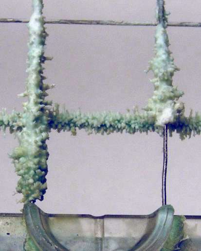 Here is a close-up photo of some severe calcification (lime buildup) on the wires of an ice cutter grid.
This calcification was thick enough and far enough over the wires that the machine would jam up and start
chugging little more than an hour after being turned on. Due to the deposits,
part of the slab was insulated from the heated wires and not being cut.
Thus part of the slab would be left behind on this part of the grid by the time the next
slab was harvested, and the new slab would come to rest higher on top of this residual ice.
When a third slab started to slide off the evaporator plate from being harvested, it was stopped
part of the way by the remnants of the first and second slabs. When the water pump started recirculating for a fourth
slab, the water ran over the third slab and into the bin, eventually depleting the reservoir to the point where
the pump intake started taking in air and making the "chug chug" sound.
Here is a close-up photo of some severe calcification (lime buildup) on the wires of an ice cutter grid.
This calcification was thick enough and far enough over the wires that the machine would jam up and start
chugging little more than an hour after being turned on. Due to the deposits,
part of the slab was insulated from the heated wires and not being cut.
Thus part of the slab would be left behind on this part of the grid by the time the next
slab was harvested, and the new slab would come to rest higher on top of this residual ice.
When a third slab started to slide off the evaporator plate from being harvested, it was stopped
part of the way by the remnants of the first and second slabs. When the water pump started recirculating for a fourth
slab, the water ran over the third slab and into the bin, eventually depleting the reservoir to the point where
the pump intake started taking in air and making the "chug chug" sound.
Grid wire calcification is not cleaned off by application of the acid cleaner and cleaning cycle to the
reservoir, because the cleaner does not flow onto the grid. Indeed, the weaker acids safe for the mechanism
won't remove this stuff from the grid at all. One simply has to remove the grid from the machine and pinch off the
lime encrustations with some pliers. They're relatively soft and will crumble off, as shown in
the photo above where the wire is exposed.
The complex fingered shape is a type of dendrite that natural mineral deposits tend to form.
The forms are actually miniature stalagmites, where the mineral-rich
used water from the reservoir has splashed onto the warm grid wires and evaporated, leaving a bit of mineral deposit
behind on each cycle, which eventually develops into the bizarre encrustations.
Some machines develop these elaborate shapes, some smooth shapes, and most have nothing like this at all.
Perhaps it has something to do with the degree of hardness of the water supply, and the varieties of calcium minerals
in the hardness. To get an idea of the scale in the close-up photo, consider that the exposed wire is about 1/40th of an inch thick,
and the spacing between the grid wires is 3/4 inch. Only a small area around the back of the grid was affected this way,
as shown in this photo of the whole grid (KitchenAid type grid),
but it was enough to disable the machine. The pastel blue-green color is likely due to acid cleaners dissolving
trace amounts of the nickel and copper in the stainless hardware.
If the cutter grid is working (the wires are warm and not calcified), the usual
cause for backed-up slabs of ice is a mechanical obstruction or mechanical misalignment which
prevents the slabs from sliding downhill and dropping properly onto
the grid when harvested.
Why the gurgling, chugging, or marching sound?
This sound is the circulation pump in the reservoir ventilating.
If a harvested slab jams halfway on its trip down to the cutter grid,
once the chilling starts again with the water recirculating, the stuck slab will
tend to interrupt the flow of recirculating water such that the water spills into the bin
and depletes the reservoir. Soon the water level drops enough in the reservoir
that the circulation pump "ventilates", that is, draws in air instead of water.
Water stops moving through the ventilated pump, and the water above the pump runs by
gravity back to the reservoir, immersing the pick-up of the pump again, and ending the ventilation.
Thus the circulation pump is alternately pumping and ventilating about once per second,
making a kind of cyclic grinding or groaning noise. With the disruption to the reservoir,
and the backup of old ice, you typically end up with a very thick slab of ice on the
evaporator plate, which is held in place by jammed ice below, with the machine
triggering a harvest in vain from time to time.
The solution is to first remove the cutter grid and clear out the backed up ice, and then
to diagnose and correct the underlying problem. Once you confirm the cutter grid is intact, is clean of lime buildup,
and is heating, you should look for mechanical obstructions or misalignments.
The problem may simply be a build-up of minerals from hard water
on the side of the evaporator plate; the routine acid cleaning procedure (see above),
or wiping it with acid and a scouring pad, should remove the build-up and
correct that. Another cause is that the top lip of the plastic reservoir bin can distort
over time such that it projects up into the path of the harvested ice, causing harvested
slabs to jam, perhaps intermittently. The solution for that is to remove the reservoir
bin and trim back that lip just a little.
Misalignment problems can also appear as the evaporator plate having moved off
its proper mounting, or the recirculation tubing having come loose and getting stuck in the frozen slab.
The gurgling noise without jammed slabs is caused by insufficient water in the reservoir
from other some other cause. Possible causes to diagnose in that case include:
- Incoming water pressure is too low or shut off.
- Incoming water line plumbing is restricted.
- The reservoir tub is cracked or otherwise leaking.
- The recirculating tube is leaking and spilling water outside the tub.
- The reservoir tub or evaporator has come loose and out of alignment, spilling recirculating water flow into the ice bin.
- The rubber-stopper drain plug in the bottom of the reservoir is loose, leaky, or fallen out.
- A too-short harvest time is not completely refilling the reservoir.
- The water supply tubing to the reservoir is too close to the evaporator plate.
The tubing freezes after several cycles and prevents fresh water from entering.
If you only occasionally get the gurgling with a fat ice slab, possibly stuck in the
path to the cutter grid, with water running over it and into the bin, then you may
have an intermittent harvest thermostat problem. If the thermostat sticks for
a cycle, the slab is never harvested, chilling continues, and you get the symptoms just
listed as a consequence. Twiddling the thickness control will unstick the thermostat,
and start the harvest, which should clear the problem.
Make sure any harvested ice slab makes it all the way down onto the grid
and doesn't hang up from being chubby.
You can also just turn the machine off for a few hours or overnight; any ice in the
upper part of the works will melt off, and you have "reset" the system.
The need for this seems to happen to my machine a couple of times a year.
-
Lost or deteriorated rubber stopper or cap in reservoir bin:
The rubber stopper (or plastic cap, like a bottle cap, in later models) in the bottom of the reservoir must not leak.
While you can order an overpriced replacement from parts suppliers,
Lowe's sells rubber stoppers out of their specialty drawers on the hardware aisle.
Measure the diameter of the hole in the reservoir.
Stoppers sizes are labeled with the diameters of the fat and skinny ends of the
taper; you want a stopper with those two diameters spanning the hole diameter.
I found a standard #2 size rubber stopper was the correct fit.
In a pinch you could improvise by carving a wine bottle cork (the cheap stuff
tends to have the hard plastic foam corks that work best for this purpose).
Use a sewing needle and dental floss to improvise a keeper lanyard if you're
worried about losing the loose plug in the ice bin.
A bit of aluminum refrigeration duct tape, Kapton electronic tape, or even cheap duct tape, stuck on the
inside of the dried reservoir, would work temporarily (or even a long time) if you can't get hold of
the stopper or cap part for a while.
Unfortunately, a soda bottle cap is an oh-so-close but no-go replacement fit to the cap thread
used on newer model reservoirs, so you'll have to pay $20 for the factory part.
The factory calls this a "nut", not a cap, which makes it a serious-money item.
So don't lose your nut.
-
Testing and replacing the evaporator thermostat with a switch and timer:
(This section applies to older machines with electromechanical controls, not the newer electronic controls.)
The evaporator thermostat is a common trouble point in older machines because
of the bracket problem described in detail above or failure of the control
itself. Since this thermostat is just a temperature-controlled switch,
and the electrical connections are easy to reach, you can temporarily replace the
thermostatic switch with a manual pushbutton to test the machine function
and diagnose a thermostatic control problem. You can also replace the thermostat
with a timer to eliminate the problems associated with the thermostat.
The thermostat control is what is attached to the thickness control
knob behind the escutcheon plate. Three 1/4-inch quick-disconnect wires attach to
the thermostat control body, which is a SPDT (single-pole double-throw)
switch. From this thermostat a capillary tube runs back to a bracket
attached to the bottom of the evaporator, where the tube senses the
evaporator temperature to remotely open and close the thermostatic switch
via the expansion and contraction of the liquid medium which fills the capillary tube.
To diagnose a thermostat problem, you can temporarily substitute a SPDT
pushbutton or toggle switch for the thermostat. With the switch installed, you manually control the
unit in freezing mode versus harvest mode. This replacement is easy
if you get a switch with 1/4-inch quick-disconnect lugs such as at an
auto parts store. Access the old control and wires by removing the
two screws holding on the plastic escutcheon cover, and then the two screws holding on
the metal bracket holding all the controls. The switch connections are BLK=common, ORG=normally-closed,
BLU=normally-open (check yours against the schematics in the service sheets linked above).
Connecting a pushbutton this way will run the
machine in the freezing mode, while pushing and holding the button for
about 2 minutes reverses the system into harvest and opens the
water valve to refill the reservoir.
If you tediously stand by to push this button at the right time,
you should be able to run cycles and make ice
Since about 2018, the electromechanical thermostats have been rare or unavailable spare parts.
I recommend that if you are in this predicament, and are capable, that you replace the thermostat with an industrial timer,
modifying the machine to run on a fixed schedule of timed cycles, instead of the machine attempting to sense the
temperature (and thus thickness) of the ice slab. A timed method makes for a simpler and more reliable operation.
You can also adjust the timer's settings, thereby manually tuning the length of the cycles to fit the condition of the machine and the ambient environment, such
that it produces an ice slab of optimal thickness.
The most direct way to perform this timer modification is to use an available industrial control timer.
These are small modules which provide SPDT switch contacts, which switch on and off according
to a timed duty cycle of your choice that you set manually using dials or buttons on the unit.
Suitable units include the Peltec 102 (about $100) and the
Altec ATS-C120 (Digikey 1920-1411-ND, $70).
If you're a fan of exotic danger and thrills, you could attempt the adventure of using a cheap import mimic of the venerable
Omron DH48S-S
($10) as competently (and indecently) reviewed AvE.
You may have to improvise cabling and an external enclosure to connect these to the ice machine,
as the larger versions will not fit in the space made available by removing the thermostat module.
It is also possible to hand-craft an electronic timer as a electronics project.
In 2009, five years after I soldered the evaporator bracket in 2004 to fix it as describe above,
the thermostat broke again, and I did not want to go through that disassembly and soldering chore again to
install a replacement part.
Now the machine had been running nearly continuously for all those years, so I imagine that solder joint
must have frozen and thawed 50,000 times (5 years times 365 days/year times 48 cycles/day times 1/2 duty-cycle),
so it is no surprise that the joint failed again.
Instead of repairing the bracket, I replaced the thermostat and capillary tube
with a low-voltage relay switch run by a 555 timer circuit, at a total cost of about
$10 in electronic parts.
The timer simply energizes the relay for 2 minutes every half hour. This timed
control gets rid of the thermostatic control and capillary tube bracket altogether (and their associated problems),
While a timer does not compensate
like a thermostatic control for variations in ambient air and water temperature,
if the machine is otherwise working properly, the half-hour cycle is a
good compromise. The ice cubes simply get a little thicker or thinner depending on
the ambient conditions.
If you're an electronics hobbyist, you can use the 555 circuit parameters I
calculated as suitable for a 28-minute freeze time and 2-minute harvest time:
R1=470K, R2=39K, C1=4700UFD.
See the schematic circuit diagram [PDF file] for this timing application from Mim's book.
A suitable miniature SPDT relay for the compressor load is Omron G5SB-14-DC12 (p/n Z1642 from digikey.com).
The evaporator thermostat functions (as indicated on the service sheet schematic and found on my unit)
for the switch terminals and wire colors are:
| Evaporator Thermostat Wiring for SPDT Switch Replacement |
Evaporator
Thermostat
Terminal |
Function |
Wire
Color |
Replacement
SPDT
Switch
Terminal |
| #1 |
Run
(to condenser fan) |
Orange |
Normally-closed |
| #2 |
Incoming AC line voltage
(from bin thermostat) |
Black |
Common |
| #3 |
Harvest
(to hot-gas and water-valve solenoids) |
Blue |
Normally-open |
You can splice onto the grid transformer low-voltage AC with a
rectifier and capacitor to supply 14VDC power for the timer.
While this was a science-fair project to assemble, replacement thermostats are getting very hard to find, and it was worth
the effort, especially after I shopped for a new machine and found they now cost $1400.
This improvised timer and relay circuit is a bare-bones control. My ideas for improving this design include:
(1) a timer reset when the bin thermostat turns off, so icemaking does not restart in the middle
of a timed cycle, (2) pushbuttons to manually start or end a harvest/refill,
(3) lamps to indicate the state of the control, (4) separate water-valve and harvest timers and controls
to limit filling to a maximum of 1 minute and harvesting to a minimum of 2 minutes,
as is done with the newer electronically-controlled machines, rather than having the water-valve
and hot-gas solenoid wired in parallel to the same control.
-
Lost calibration on evaporator thermostat cut-in and cut-out:
(This section applies to older machines with the electromechanical controls, not the newer electronic controls.)
The evaporator thermostat has screws to adjust the cut-in and cut-out temperatures.
Typically the control does not indicate the polarity of these adjustments,
that is, which way to turn these screws to make the respective settings warmer or colder.
The multiple independent adjustments require a bit of procedure to
deduce the polarity.
A new control part should include a data sheet describing the
calibration process. If you don't have that information,
or you are trying to recalibrate an old control, then
you'll have to analyze the
behavior to learn the polarity of the cut-in and cut-out adjustments.
If you have a loose control unit (out of the machine), you can
characterize it as follows:
-
Make up a bowl of warm water and a bowl of sub-freezing slurry
(crushed ice with salt, or crushed ice with non-toxic antifreeze)
to impose a thawed versus sub-frozen temperature on the thermostat probe.
-
Make up a grid chart of 25 trials, combining 5 possible trial settings on
each of the two adjustment screws. Using a screwdriver on each adjusting
screw, determine the range of how many screw turns the adjustment provides.
The trial settings should cover this range, starting with full counter-clockwise,
then 25 percent clockwise, 50 percent clockwise, 75 percent clockwise, and full clockwise.
-
For some grid cell, adjust the screws to a trial combination and test
the continuity of the control for open or closed, with the probe inserted
in the warm and cold bowls respectively. Record these two results in
the grid cell. Repeat for all 25 grid cells.
-
When you have filled the chart, analyze the results to determine the
polarity of the cut-in adjustment (adjusting clockwise makes it warmer, versus colder) and cut-out
(likewise). The region of the grid that has the control contacts closed
for warm temp and open for sub-freezing should indicate suitable starting settings for
the adjustment screws.
-
Install the control and observe some cycles to adjust the cut-in and
cut-out temps for proper cycle times.
To recalibrate the control while it is installed in the machine,
start by checking continuity of the control contacts
with a warm machine and the two adjustment screws in each of the four combinations of
extreme adjustment. The combination(s) with closed continuity will be candidate(s)
for the initial adjustment. Set the adjustment to such a candidate,
start the machine, and wait for a slab to freeze.
Back-off the cut-out screw from its extreme setting until the harvest triggers.
Wait a minute or two for an appropriate time of harvesting,
and back-off the cut-in screw until the chilling triggers. Note the polarity
of these adjustments, that is, which way of turning each adjusting screw makes the respective
action occur a warmer or colder temperature. Note also the number of turns in the
full range of adjustment. These notes will help you fine-tune the settings now
and in the future.
I've heard some controls have only one screw for adjustment. In this case the
range between cut-in and cut-out is not adjustable, only the temperature limits where they
apply. The recalibration procedure is then a subset of the above.
- Bin fills up with water or drains slowly:
If you have water collecting in your ice bin, you might woefully conclude that your drain connection is
clogged, and that you're going to have to tear the machine out of the counter to get to the drain plumbing.
It might not be that bad.
Unlike a regular sink drain, slow draining is not usually caused by the household drain line or
trap being clogged. Usually it is caused by bits of debris that have fallen into the bin
and collected in the small drain sump and drain passage at the back of the plastic ice bin.
Since people are bending over to reach the bin, all kinds of stuff can fall in and get lost
in the ice, and eventually it works its way down and back to the drain.
I found out (the hard way) that 6mm toy airsoft BB's are a perfect plug fit for the drain
passage at the bin sump.
The problem with this clog diagnosis is that it can be difficult to inspect the drain passage at the
back of the bin. It is not difficult if you can access the rear and disconnect the drain hose,
but it you have an undercounter installation, this requires tearing out the machine from the
cabinetry. Short of that, a flashlight and inspection mirror can help you inspect back there from
inside the bin, and loose items in the sump can often just be vacuumed out.
But if you have something jammed in the narrow passage at the bottom of the sump, something that
fits snugly (like my experience with the plastic BB), then you have to access the back of the
machine, remove the drain hose, and sound the passage, from the outside in, with a stiff wire to clear out the
trouble.
You should not ignore water collecting in the bin,
because you have a potential overflow and flood on your hands
if the solenoid valve should stick open.
- Condenser fan intermittently does not run:
If you have the electronic controls, the fan has its own relay on
the PC board. So if the fan fails intermittently, the fault could be the fan itself, the wiring, or the controls.
Splice a test lamp into the wires to the fan to distinguish the fan itself vs the wiring or controls,
and wait until the fault appears to diagnose the intermittent cause.
The shaft bearings in the fan can get slightly fouled up and the fan
won't start sometimes because the starting torque is very low. If the
fault appears, see it you can't spin the fan blade by hand with a probe
to get it to start. This requires a replacement of the fan motor since
the cheap bronze sleeve bearings aren't serviceable.
- Condenser fan makes loud buzzing noise:
The condenser fan, found in the bottom of the unit, circulates room air across the
condenser coil and exhausts the warm air. The rotating fan blade is surrounded by a rather
flimsy folded fiberboard shroud that can distort in shape, such as from age or from getting
wet. The shroud can contact the fan blade and make a loud buzzing noise. The solution is
simply to adjust the shroud or trim it back so it doesn't contact the moving fan.
This can be difficult to reach if you don't have access to the rear of the unit.
Another fan shroud solution is to craft a replacement from a sheet of stiff, thin plastic.
Suitable material is cleverly hidden in disguise at your local building supply retailer
as 2' x 4' drop-in panels for fluorescent lighting fixtures.
Mark Egan has generously originated and contributed this
EC5100 fan shroud drawing [20 KB PDF file, 1 page]
which gives a pattern for you to cut and fold.
UL-listed aluminum foil duct tape, which is designed to endure hot and wet conditions,
is suitable for assembling and fastening the folded construction, and can be found
at the same building supply.
- Waterlogged insulation:
I've heard reports that some machines develop "waterlogged insulation".
The dry fiberglass blanket and vapor barrier around the bin are critical to good performance.
If this insulation becomes wet, it no longer insulates; then the ice produced will melt quickly.
This is a pernicious problem in that the insulation may never dry out:
lack of insulation may cause the temperature of the exterior surfaces to fall
below the ambient dewpoint, so that moisture continually condenses on the outside of the machine, keeping it wet indefinitely.
Initial causes of this type of insulation failure include plumbing leaks (in the machine itself,
or possibly from other appliances nearby in the cabinetry), a cracked bin leaking
water from melted ice, and a detached blanket or vapor barrier allowing water to condense on the outside of the bin.
Testing for failed insulation requires that you simply feel it by hand for moisture.
The repair is to correct the underlying problem, and shut down the machine long enough to
dry the outside thoroughly. Moral: keep the blanket snug and the vapor barrier intact.
Later designs put the insulation into sealed plastic bags to prevent this problem from developing.
These "pillows" of insulation then stuff into the gaps between the plastic bin and the metal cabinetry.
- Ice melting from splashing water:
Besides failed insulation, another problem can cause your precious ice to melt too fast in the bin,
namely that warm water is splashing out of the upper apparatus and down onto your finished ice cubes.
Another sign of this problem is that the cubes get a pebbly or honeycombed texture after sitting
in the bin for a while.
This is hard to detect with the grid in place, since the splashing water will tend to just drip down
slowly like the normal dripping from cutting the slab into cubes.
So remove the grid and run the machine, then shine a flashlight into the upper area of the
bin to see if you have a very fine rain of water splashing out of the upper apparatus.
One cause of this splashing is mineral deposits in the passages of the water dispenser tube,
causing the recirculating water to squirt too forcefully against the top of the evaporator.
In this case an acid cleaning should take care of the minerals.
One would hope this works, because removing that tube for service is difficult.
- Dripping water in base of machine:
Several problems can cause water to be dripping slowly into the
bottom of the machine.
You could test for a cracked bin or drain problem by turning the machine off and
emptying it, plugging
the drain, and filling the bin with water to see if it drips or not. You might
also test look for stray water from the water recirculation circuit since it
would drip or not drip with the machine running or not (you might
have a broken, displaced, or cracked part in the recirculation path).
Another possibility is missing or waterlogged insulation beneath the bin,
resulting in condensation outside the bin (see above). There can normally be some
condensation on the refrigeration return tubing, but this doesn't drip
that fast.
- Evaporator bracket repair kit:
(This section applies to older electromechanical controls, not the newer electronic controls.)
An email correspondent writes that, "Whirlpool came out in January 2006 with a
evaporator bracket repair kit (part number 8201758). This came out on
their Service Pointer Bulletin R8178560, January 2006. I hope this helps
you or others to repair this failure."
Another correspondent reports that,
"The bracket is same shape and size as the original bracket and is held
against the evaporator by a support (approximately 1 in wide and shaped
similar to a V) that is fitted over the heat exchanger tube. ... Would appear that a
person could clean up the old bracket and devise his own method of wedging it to the evaporator."
He includes Whirlpool's instruction sheet for Evaporator Support Bracket Re-Location [424 KB PDF file],
and reports the price is about $30 (try online sources or local appliance parts retailers).
Being that this is merely a small, V-shaped metal clip with a hole in it, I would suggest improvising something
from some thin stainless steel to save yourself $30 (and save having to search the cosmos for this item).
You might find suitable material on a cheap kitchen tool that you can cut
with tin snips, and then punch or drill a hole into it.
In fact, a polyethylene plastic clip that you can cut yourself from something heavy like an empty laundry
detergent bottle might even work as well as anything for this purpose.
The photos in the instruction sheet make clear the type of wedging action you are trying to create.
I'm a bit dubious about this kit and how it wedges the clip against the heat exchanger tube;
this would seem to chafe the soft metal tubing with the hard stainless clip under the normal vibration
of the machine, and this I expect would soon cause a catastrophic refrigerant leak.
Or perhaps in practice it holds up fine; I just have no experience on this trick.
I suppose we should be encouraged that Whirlpool, after so many years,
isn't forcing you to buy an entire evaporator to repair a loose solder joint.
- Missing overflow tube can spoil ice production:
I've explained how, during the harvest cycle, excess tap water flows into
the reservoir to flush out the concentrated minerals in the "used" water.
Normally a polyethylene tube feeds the warm water from the overflow
outlet down to the drain sump in the back of the bin. This tube can be
accidentally knocked off. Being polyethylene, it can get brittle over
some years and crack into pieces. This simple piece of tubing might not
seem like an important component to worry about. However, without it,
the warm overflow will run over the ice already delivered into the bin,
melting some harvested cubes and spoiling your ice production. So make
sure this tube is in place.
- Drainage and drain pump issues:
The standard installation for this type of ice machine assumes you
have a house drain connection either in the floor or lower on the wall
compared to the bottom of the ice bin. This maintains a downhill path
for the ice melt to run to the bottom of the ice bin, out of the machine,
and down the house drain. If your available connection to the house
drain is above the level of the bottom of the ice bin, then you have an
uphill path for melt drainage that requires an extra pump to remove.
Some residential ice machines sold today have drain pumps built in as
standard equipment, but this was not a feature of the electromechanical
Whirlpool models.
The extra pump for uphill drainage is typically an optional sump
pump that is installed in the lower rear of the ice machine.
These pumps are quite expensive if purchased from an appliance
parts dealer, but they are nothing more than what is usually
sold as an inexpensive air conditioner condensate pump, such as
Grainger
item 2P350 ($46 in 2006) which is a Little Giant brand (Web site), model VCMA-15ULS, HVAC
condensate removal pump.
Home Depot (search for "condensate")
listed a Flotec model FPCP-20ULST condensate pump for $53 in 2006.
Such mechanisms consist of a shoebox-sized
plastic box that acts as a sump to receive incoming drainage water, with a
float valve sensing the water level in the sump box and activating a small
pump to occasionally empty the sump box as it fills. Another Little Giant
model is the VCMA-20ULS, which features a 20 foot lift capacity instead of
15 feet, although lift capacity is not important for this application.
Comparable pump models are made by Beckett (CB151UL or CB201UL) or
Hartell (KT-15X-1UL or KT-20X-1UL). Any of these are suitable for ice
machine drainage.
Note that the drain pump is not typically configured to interrupt the water supply
at the solenoid valve if the pump fails, or if other drainage problem
arises such that the sump level overflows. You will therefore face
a slow but mysterious water leakage someday when your mortal drain pump
fails, so you should plan the installation accordingly. That is, consider
installing the pump to facilitate easy inspection and service access.
If you can, also arrange things so leaking water won't damage something
that is expensive to fix.
While I have seen them installed in the hollow volume at the lower
rear of the ice machine, it makes more sense to run the bin drain to an
adjoining cabinet where the pump is more open for inspection and service.
You will still have to obey the law of gravity in placing the pump lower
than the bottom of the bin drain.
Since these pumps and drains all eventually develop problems, you don't
want to have to pull out a heavy machine with great difficulty from
built-in cabinetry for these maintenance tasks.
Some drain pumps provide an overflow interlock switch that turns off
the ice machine if the sump fills up with water due to a failed pump
or clogged drain. This is something to consider troubleshooting if you have an intermittent
or otherwise unexplainable problem with your machine, such as it randomly turning off and
back on to power-on reset conditions (such as the 5-minute flush of the electronically
controlled models). This overflow switch is a "feature" that is supposed
to save you from flooding the floor; don't let it trick you into thinking
your machine has failed.
Unlike air conditioning condensate, ice-melt water is not contaminated
with a lot of dust to support microbial growth, and the drain lines
do not typically clog up over time from algae like can happen with
air conditioners. So you don't need to worry about cleaning them
periodically such as is needed with air conditioners. This applies
to both gravity and pumped drainage. If you do experience a clogged
drain, see the discussion of "Bin fills up with water or drains slowly"
above for other possible causes.
- Diagnosing and repairing fan problems:
The fan in the refrigeration assembly in the bottom compartment of the
machine moves a small volume of air through the machine to cool the
condenser coil and exhaust heat from the machine. If this fan quits
moving air, then the compressor will run but the machine will not produce
ice. If convection currents of air happen to exhaust some heat slowly,
it may produce ice very slowly with hot air percolating out slowly from
the bottom of the machine. If the compressor overheats, the overload
switch may cause it to shut off until it cools.
If you find that the fan is not running when you expect it to be,
you have to diagnose between the possibilities that (1) the machine is
wrongly stuck in the reverse part of the cycle (hot gas heating of the
evaporator to harvest the ice slab), when the fan is not supposed to
run but the compressor does, meaning you have a control problem, not
necessarily a failed fan, or (2) the machine is in fact in the chilling
part of the cycle, with the compressor running, but the fan is not moving
air due to a problem either with the fan itself or its wiring or controls.
Once you diagnose that you are in the second case (an actual fan problem)
you must diagnose whether the fan itself is failed, versus its wiring
and controls. You might try to reach in the machine (of course, when
it is turned off) and feel if the fan blade turns freely; the fans in
the ice machines don't seem to often fail, but I know that in window air
conditioners that a similar type of fan can get sticky bearings that keep
the motor from starting. Another thing to check is that the paper shroud
or some foreign object isn't simply blocking the fan blade from turning.
As a last test you can hot-wire the fan to see if it runs, either by
tracing back on the wiring diagram to the connector at the control, or by
directly cutting and splicing into the wires at the fan itself. The space
is very cramped and the fan is difficult to reach, but its replacement is
more difficult and you need to be sure that the fan itself is the problem.
Another diagnostic trick if you suspect the fan simply is not running when
it should, is to improvise some kind of air flow across the condenser
coil with another small fan, some flex duct on an air-mover fan, a big
shop vac suctioning the exhaust side of the condenser, or the like.
You don't have to do a perfect job of this as long as some air is moving
across the condenser and out of the machine. It doesn't take much air
moving to prove that the chiller works and is making ice, if the problem
is simply a dead fan.
Replacing the fan is difficult because of the cramped space and the
compressor being in the way. The entire lower refrigeration unit is
designed to slide out as an assembly on its sheet metal base if you need
to replace it or work on it. The fan cannot be removed directly from
the machine, as it is boxed in by other components and sheet metal.
However, there is enough slack in the copper tubing connecting the
compressor and evaporator to unbolt those items, or the entire lower unit
tray, and gently manipulate them out of the way to remove and replace
the fan.
One correspondent suggests that the fan can be easily replaced from
the front as follows: Remove the screws holding the condenser coil and
capillary tube brace to the chassis; Move the condenser coil to the side
a little. Use a 7/16 inch socket with a long extension to remove the
motor mount screws; Push the condenser coil over to the right and wiggle
out the motor with its mount. I'll agree that this manipulation looks
plausible, although I haven't tried it myself.
Another possibility for removing the fan is getting to the fan from
the side or behind the unit. You have to cut a section out of the
sheet metal side or back to get to it. If the machine is installed
under kitchen cabinets you don't need those sides anyway.
- Water condensing and dripping from the drain line:
Since the drain line contains chilled water, it can condense humidity on the
outside of the line and drip water, if the drain line runs through a humid space,
such as through the floor into a basement. The best solution I know to this problem
is to spiral-wrap the drain line with "No Drip" brand tape made by Mortite. This is a thick, sticky-gooey
wrap that insulates well enough to prevent condensation, and stands up to moisture without
disintegrating or losing its insulating properties.
The putty-like consistency of this stuff lets you mash and mold it into a
vapor-tight jacket after you wrap it in a spiral around the pipe.
Sold at Home Depot or Lowes with the air conditioning mechanical items.
Air conditioning installers use this to insulate condensate lines, so you
might also find it at an HVAC supplier.
You can also find insulating wraps made from foam, cork, or sponge rubber, but
this old-fashioned Mortite stuff is my choice for price and effectiveness.
Similar stuff is sold as Presstite Permagum
and Virginia KMP sealing compound.
- Sanitation issues:
Sometimes I get inquiries about the sanitary aspects of ice machines.
You hear bad publicity about restaurant ice bins being contaminated.
This should never be an issue in a household machine, if you simply
avoid introducing contaminants into the bin.
The crystalline process of forming ice sorts out pure water from
dissolved or particulate contaminants. Water molecules lose their
heat of fusion and "stick" to the chilled ice surface in the laminar flow
on the surface of the slab; anything else but water tends to just keep washing by.
This selective fusion of water molecules inherently avoids entraining microbes
into the ice. The clarity of the ice is evidence of its purity.
Even if the reservoir water is not sterile, the ice itself is, or
very nearly so. The constant freezing temperature inhibits microbial
growth, the reservoir water supply does not contain any nutrients to
support microbial growth, and city water should have enough chlorine or
chloramine sanitizer to kill any slight microbial contamination and keep the water sterile.
Since the ice in the bin is completely replaced at least every few days (by melting if not
by usage), any dirt, dust, or other contaminants
in the bin tend to quickly wash or work their way down to the bottom
of the bin towards the drain. So you can be confident
that your ice starts out clean, and if you don't foul the bin, your
supply of ice in the bin should be clean.
- Replacing the lamp:
Later models of the machine feature an interior lamp controlled by a door switch.
This is similar to a 12 VDC automotive type socket and lamp. If your
old lamp or socket fails from corrosion, instead of paying $100 for the Whirlpool item,
you can splice in an LED, like an 12VDC LED accessory lamp from
the auto parts store. Boat stores (West Marine, Boater's World, Bass
Pro Shops, etc) also have water-resistant 12VDC LED accessories to use
for improvising.
- Replacing the evaporator on electronic models:
For KitchenAid and other electronic models,
see the instructions on replacing the evaporator
contributed by Brian Christal.
- How much water goes down the drain for how much ice?
Above we calculated that each harvest produced 18 ounces of ice and admitted about a gallon of water
to flush and refill the reservoir per cycle. At maximum production (30-minute harvest cycles over 24 hours equals
about 48 cycles per day), this means the machine is using roughly 50 gallons of water per day to
produce 50 pounds of ice. About 44 of those 50 gallons go straight down the drain during harvest flushing.
This is the overhead cost of demineralizing water via freezing to yield clear ice.
For typical household users, a substantial fraction of the remaining 6 gallons worth of ice ends up melting and going down the drain, too.
This is the overhead cost of the convenience of having a ready ice supply in wet condition.
If water conservation is critical, one could capture the (clean) waste water via a
condensate pump for other uses (like irrigation), and one could store the finished ice in a
freezer so it didn't melt. Consider that restaurant ice machines work on similar principles,
wasting a lot of water.
- Diagnosing flashing lights and shut-downs with electronic controls.
Later models with electronic controls, including the KitchenAid models,
can flash a few simple coded messages and shut down when the control board detects a problem.
In normal operation, if the machine shuts off and
flashes the LED lamp on/off in half-second increments, this indicates that the harvest lasted longer than 16 minutes.
This typically is due to a faulty evaporator thermistor or its connection, although it can be caused by a problem in the
hot-gas reversing valve or its controls.
Flashing in one-second increments indicates the bin thermistor or its connection is faulty.
Further diagnostic codes are available if you switch the unit into its clean cycle by pressing the CLEAN button:
the first thing the control board does in the clean cycle is test the thermistors for
proper connection and resistance, and if found faulty the control board will flash the LED
two times for a faulty bin thermistor, and/or 5 times for a faulty evaporator thermistor.
If you unplug either or both thermistors completely, you should also observe these flash codes at
the start of the clean cycle.
Note that these codes were programmed as part of a later version of the electronic control board first released in 2004,
so you may or may not have this feature in your unit (see the item with "check which version" in the list below).
Other features of the later version include:
- 15-minute minimum and 25-minute maximum refrigeration time to avoid slabs too thin or thick.
After 25 minutes the unit will force a harvest regardless of the thermistor sensing.
If you have poor refrigeration performance, this will therefore cause thin slabs to be harvested.
- Refill time 1-minute maximum to reduce water use and avoid a valve stuck-open condition from
failures in the evaporator thermistor or reversing valve.
This means if you have a water supply restriction, you may get cloudy ice or chug-chugging from insufficient refilling.
- Fall-back 25-minute freeze and 4-minute harvest if the evaporator thermistor is unplugged or giving faulty readings.
- 16-minute maximum to harvest before shutting down for evaporator thermistor failure.
This means you can get exactly one slab total harvested when the machine shuts down.
- Thermistor checks performed at the beginning of the clean cycle diagnostics instead of at the
end (and presumably you can use this to check which version you have).
- Diagnostic clean cycle starts with both freezing and recirculation pumping instead of just freezing to avoid sticking
an old slab to the evaporator and causing a jammed slab during the cleaning cycle.
(you can use this to check which version you have, the old version clean cycle diagnostics will first run the refrigeration with no recirculation for 30 seconds).
- Minimum harvest time of 2 minutes, with evaporator thermistor temperature sensing evaluated at the 2-minute mark
instead of continuously from the start of harvest.
This will prevent some marginal thermistors from causing a shutdown, at the expense of less frequent cycles and thus reduced performance.
The above list was based on Whirlpool Instruction Sheet 4388700 Rev A 6/04 (view that document).
Remember the following points when diagnosing these flashing trouble codes:
- The evaporator thermistor may have failed or it may be erratically responding. You can disconnect the
thermistor and restart the machine to see if the unit operates properly in timed mode.
You can also remove and test the disconnected thermistor with an ohmmeter
for proper resistance values at various temperatures as explained in the service manual.
- Likewise the bin thermistor. The unit apparently will not run with this disconnected, since it
might lead to overfilling the bin and spilling ice out onto the floor.
You can "cheat" the bin thermistor with a 10K ohm or 22K ohm (or
thereabouts) resistor (such as from Radio Shack). This is a cheap way to test that the machine
runs if the bin thermistor is suspect, since the replacement thermistor is expensive.
- The white plastic connectors or the crimp connections for these two thermistors
can also fail or become intermittent.
- If equipped with a drain sump pump, the overflow interlock switch can intermittently
shut the machine down, when there is slow drainage or a failure of the pump.
- What if the circulation pump bracket comes loose with stripped threads:
In older machines you may find that the a failed pump also has come
loose from a corroded mounting bracket. While you can replace the pump,
the brackets are not to be found as a ready replacement part. Oh, no!
What to do?
You must take the initiative to improvise this type of repair with your own
mechanical skills. This isn't so difficult. One has to set aside the habit
of assuming that fixing something is necessarily a matter of finding just the part you need.
Often you can fix things better yourself with a little ingenuity.
Note: This is actually good advice for many things in life,
and an article of faith in my do-it-yourself credo.
Women find this intrepid elan attractive in a man;
chicks dig guys who can fix things.
Your ability to understand mundane technicalities
suggests you might be able to understand the mysteries of womanhood.
If you replace the expensive Whirlpool brand pump with the inexpensive aquarium pump as described above,
you don't need the bracket at all, since the new little pump
will just sit in the bottom of the reservoir bin. You will have saved
some $$$ as well as fixed two problems. Or, enlarge and tap the
stripped holes in the old hardware with a larger thread size to reattach
the old bracket with larger screws. Or, drill through the back wall and
put some nuts and bolts through to hold on the old bracket and pump.
Or, cut/drill/tap a new bracket from a bit of aluminum or stainless
(like from onlinemetals.com, or
maybe just taken from an old cookie sheet or kitchen tool).
To improvise this type of bracket, another method is to
saw a block of high-density polyethylene (HDPE) into the specific size from bulk material.
HDPE is easy to saw by hand, and to drill to receive self-tapping stainless screws.
This material is cleverly hidden in disguise
as a cutting board for the kitchen at your local retailer.
Or search for "HDPE" or "UHMW" at onlinemetals.com.
- PC (printed circuit) board typical failures:
The printed circuit board (PC board) (see close-up photo) that implements the newer electronic controls
is a typical cause of failure, often of a frustratingly intermittent type of malfunction.
Several people have been kind enough to send me their
failed boards for post-mortem analysis, and what I have often diagnosed is simply
that a solder joint cracked on the printed circuit traces. This is easy to repair
with nothing more than a touch of a soldering iron, which repairs this costly replacement part.
Look carefully under magnification at the solder joints for the relays, especially
the compressor relay which handles the most power. If you wiggle these components
you may discover a broken or cracked solder joint. The relays click and bounce
on every actuation, handle a lot of watts, and experience wide temperature cycling,
which makes the solder connections vulnerable to failure. A cracked joint can make
and break contact to make the malfunction intermittent. Removing the PC board for
for an inspection is a chore, but it may turn up the cause of a control problem
that isn't due to a failed sensor or wiring.
The relays themselves may fail, in which case an inexpensive replacement is
an Omron G5LE-1A4-DC9
(such as from mouser.com).
The compressor relay is Potter and Brumfield T9AS1D12-9, available from
digikey.com.
- On diagnosing intermittent problems:
Intermittent malfunctions are always more difficult, because diagnostic
tests may misleading if not made during a malfunctioning moment.
Since one must make diagnostic measurements when the malfunction actually occurs.
you have to sit and patiently wait for the event.
On an ice machine which takes 20 or 30 minutes to cycle, this can involve
a lot of patience.
In such circumstances, I would hook up
an indicator light or other visible indication of the test measurement
and hope to see it when the fault occurs, while pursuing some other pastime
nearby. Or maybe run a long video recording of the
machine showing the test indicator, and then rewind to witness the
actual malfunction, after-the-fact. You can also use a data-logging voltmeter that
connects to a PC, which can even be had cheaply at Radio Shack these days,
to perform quantitative time-domain recording.
- How effective is cleaning:
The cleaning features are rather a hoax. The lime buildup occurs exactly
where the recirculating water doesn't go, which means the cleaning
solution doesn't go there either. There's nothing you can just swish in
there to get it really clean. It does appeal to the appliance customer
if there's a magic button that purports to do the cleaning for you.
If you have mildew looking residue on or in the tubing, it is possible
that Whirlpool has used tubing with plasticizers which support microbial
growth, which I've seen in other contexts, and the growth will be infused
into the plastic itself and never will truly clean, although it will
be encapsulated so it isn't an actual problem. The only way to really
clean these machines is manually with a toothbrush and disassembly, very
laborious, and replacing tubing or other infected components.
A solution of lye will do better in cleaning mildew or other organic residue,
as opposed to mineral deposits which are best cleaned with acid.
It might be
best to just pretend it isn't there and not look inside that carefully.
The recirculating water itself tends to rinse everything clean that
it touches.
- Mothballing:
To shut the machine down for an extended period, first turn off the power.
Close the water supply shutoff valve. Pull the
plug on the bottom of the reservoir to drain the water out, and dry the
rest of the machine as convenient, and then leave the door open at least
a few days so the inside dries out thoroughly. Otherwise the bin will be wet
and warm inside, and it can get musty in there. You may need to replace the
reservoir rubber stopper if it has deteriorated. To start running again,
turn on the water supply, check for leaks.
This is a good time to remove the grid and reservoir bin, and acid clean them by hand
if you are so inclined.
Turn the machine on.
It should cycle and start dropping ice cubes in 45 minutes or less.
The first cycle or two worth of ice should be discarded if the ice has picked up bits of
lime deposits flaking down into the reservoir from the drying out.
- Shipping these ice machines:
Someone wrote me to ask, "I have one of these units I'm going to sell on eBay. Would you mind
telling me any good or bad experience you may have had in shipping one of these?" I replied
as follows:
I bought boxes (26 x 20 x 30, 275 lb test, double wall) to fit them.
For each, I cut a plywood
base panel that just fit inside the bottom of the box, and bolted down the unit centered
on that, and hot glued the plywood panel to the box. I also built gussets to
fit and reinforce the sides and corners of the machine into the box, by cutting more corrugated cardboard and
assembling with more hot glue. Rather costly and time-consuming, but
well done, I thought.
I would ship them by ground using
[a certain shipper best known for overnight air delivery] as the cheapest way.
They lost one unit completely and admitted it. To get the insurance claim
paid took me hours and hours of silly paperwork. Hardly worth the
recovery.
They ruined another unit and I never learned how. It arrived intact but
with the refrigerant leaked out and with oil staining the box. The recipient
mistakenly accepted the shipment without noting the damage. The recipient
then paid an appliance service to come out and diagnose the unit, and
tried to get [the carrier] to pay the a damage claim for the repair estimate, but gave up
after being presented with the bureaucratic challenges.
Most of the units arrived OK. But those two were nightmares.
Maybe UPS or DHL would have done better than [the carrier]. Or even LTL truck freight.
So if you want to ship one, be ready to take on a woodworking and craft
project to crate it properly, and prepare yourself for disappointment
despite your best efforts.
- Scotsman: Scotsman is a staid old American brand for ice machines.
Their Web site at http://www.scotsman-ice.com/
includes a page where you can
download manuals.
The models beginning in "CS" are household units.
The model CSWE1 appears to be a rebranded Whirlpool unit, and the
downloadable owner's manual (15-page PDF file)
may be of interest to anyone with a Whirlpool machine.
- Don't Know Much About Other Makes and Models:
If your unit is another make or model that doesn't resemble the
Whirlpool-manufactured units shown in the parts diagrams linked above,
then I don't have much advice for you other than the general principles above.
Chinese manufacturers like Haier seem to be importing large
quantities of residential ice machines at prices much less than Whirlpool ever
charged (for example, search for "ice machine" at Home Depot, although
this seems to have gone away sometime in 2008),
but I have yet to inspect these models enough to have a knowledgeable
opinion of their quality.
- Disclaimer:
I operate independently of the manufacturers and trademark owners mentioned above (Whirlpool, KitchenAid, etc.).
I reference these trademarks solely to help you to identify these machines, to understand their various qualities and technical principles, to diagnose their problems,
and to inform you of compatibility of my parts and services with various products made by others.
I have no business relationship with these manufacturers, and receive no compensation from them.
"Bene diagnoscitur, bene curatur."
—Latin proverb
Translation: Good diagnosis, good repair.
Have a comment or question about my ice machine repairs?
Need to thank me for saving your expensive ice machine from the junk pile?
Email me at:
kinch@truetex.com
Richard J. Kinch
Back to Machine Shop page
Back to Home page
Copyright 2004, 2005, 2006, 2007, 2008, 2009, 2010, 2011, 2012, 2013, 2014, 2015, 2016, 2017, 2018, 2019, 2022 Richard J Kinch
First edition: 2004
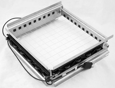
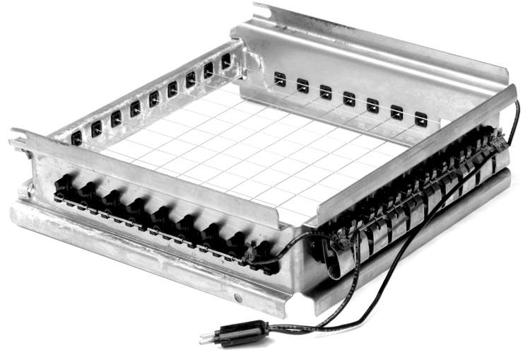
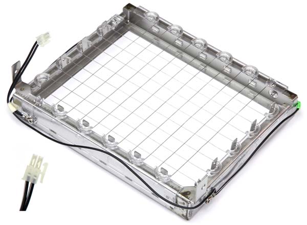
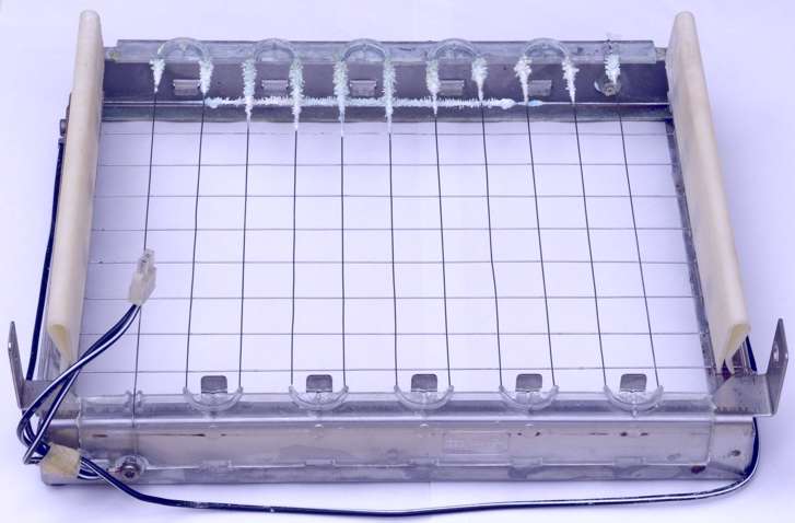
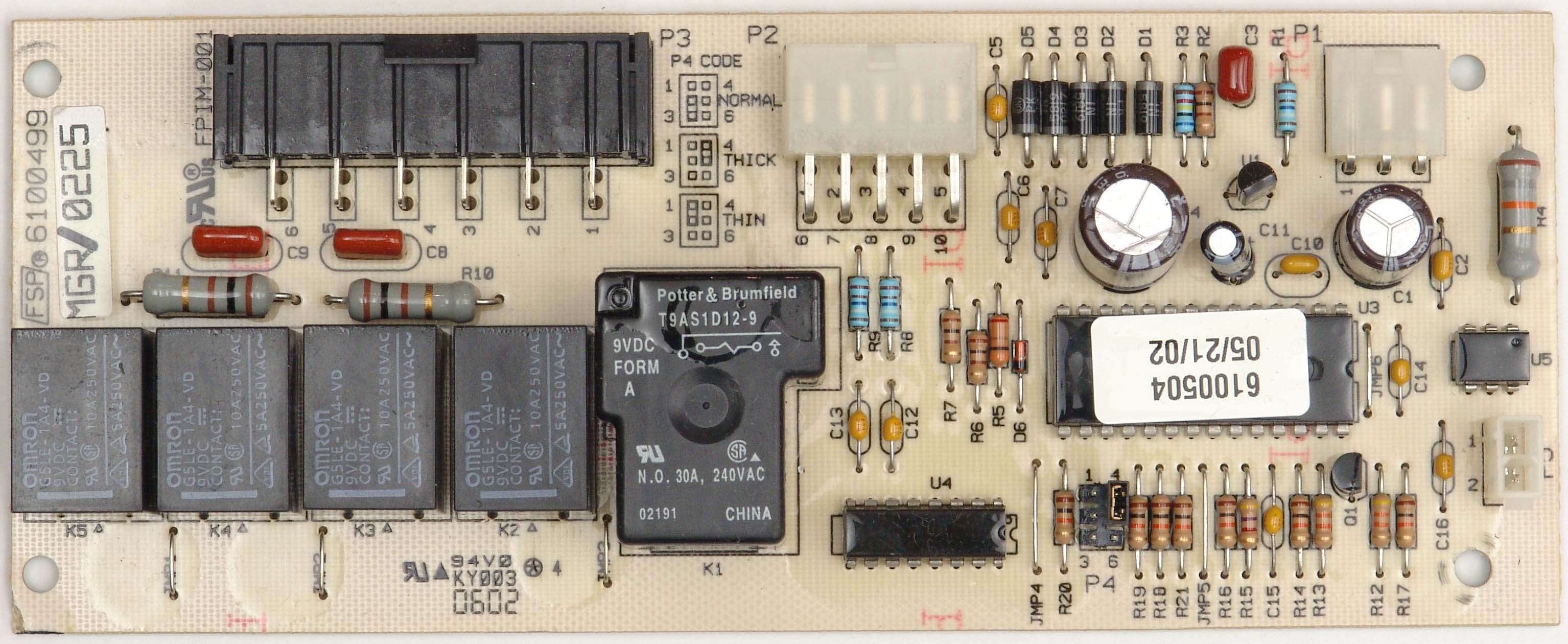